The filter and shunt capacitor device test is a project that needs to be carried out after the equipment is newly installed or after the equipment is powered off. After the equipment is newly installed, the construction unit needs to carry out a handover test, and after the equipment is overhauled, routine tests or special tests need to be carried out. According to the time stage of equipment operation, the test items are divided into handover tests for newly installed equipment, regular routine tests, and diagnostic test items based on the equipment status. The following introduces the test items carried out for the filter and shunt capacitor device.
1.Handover items for filter and shunt capacitor device test
1.1 Handover test of capacitors
The test of capacitors is mainly to check whether the inside of the capacitor is damp, whether the capacitor elements have breakdown short circuits, and insulation degradation. Mastering the correct test methods and carrying out reasonable test items can not only reduce the workload, but also detect defective capacitors in a timely manner. Since capacitor failures account for the majority of the failures of the entire filter and shunt capacitor device, capacitor device test is particularly important in the entire filter and shunt capacitor device.
(1) Insulation test of capacitor device test. Any electrical equipment can monitor the insulation condition of the equipment by measuring insulation resistance, dielectric loss angle, partial discharge, insulating oil chromatography and AC withstand voltage.
The insulation resistance is generally measured to test the insulation of capacitors at the construction or maintenance site. Usually, only the insulation resistance test of the pole to the shell is carried out on site (the inter-pole insulation resistance test itself has no practical significance). To measure the insulation resistance of the pole to the shell of a single capacitor, first connect the two poles with a wire, and then use a 2500V insulation resistance meter to measure the insulation resistance of the two poles to the shell, as shown in Figure 1. The insulation resistance value is generally above 2000MΩ. The insulation resistance test of the two poles to the shell can check the insulation status of the pole to the shell. This test item can be used with an insulation resistance meter or a digital insulation meter. The test is simple and convenient, and is more effective in checking whether the bushing is damp. The standard requirement for the insulation resistance of the pole to the shell should be greater than 1000MΩ.
However, in actual field projects, many capacitor device test often involve insulation resistance tests, and testing them one by one may not be possible in terms of time. The usual practice is to short-circuit all the leads of the capacitors to be tested (as shown in the wiring diagram in Figure 2), and then perform insulation resistance tests on the entire device. If it is found that the insulation of a group of capacitors does not meet the requirements, the group will be tested one by one.
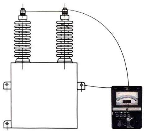
Figure 1 Schematic diagram of capacitor insulation resistance measurement
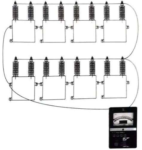
Figure 2 Insulation resistance test of a large number of capacitors
(2) Capacitance test of capacitor device test. Capacitance is a major technical parameter of capacitors. Although its test is not complicated, it is indeed the most common test item in filters and parallel capacitor devices. Only through capacitance testing can the faulty capacitors in the entire capacitor tower be located and replaced. The significance of measuring capacitance is to check whether the actual capacitance of the product is consistent with the nameplate. If the capacitor has undergone an inter-electrode withstand voltage test, capacitance tests should be performed before and after the test to check whether the small internal series and parallel components are damaged during the test. The internal components of the capacitor in operation may be short-circuited or open-circuited. This section only describes the measurement of the capacitance of a single capacitor. For a DC converter station under the influence of a complex electromagnetic environment, how to locate the faulty capacitor on the entire capacitor tower will be described in detail in Chapter 5. The methods for measuring capacitance in capacitor device test include voltage and current meter method, digital capacitance meter method, and capacitance bridge instrument method.
In converter stations, digital capacitance meters (as shown in Figure 3) and capacitance bridge testers (as shown in Figure 4) are often used to test capacitor capacitance. The following details the capacitance test method and steps for capacitor device test using digital capacitance meters.
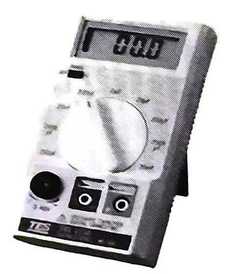
Figure 3 Common digital capacitance meter
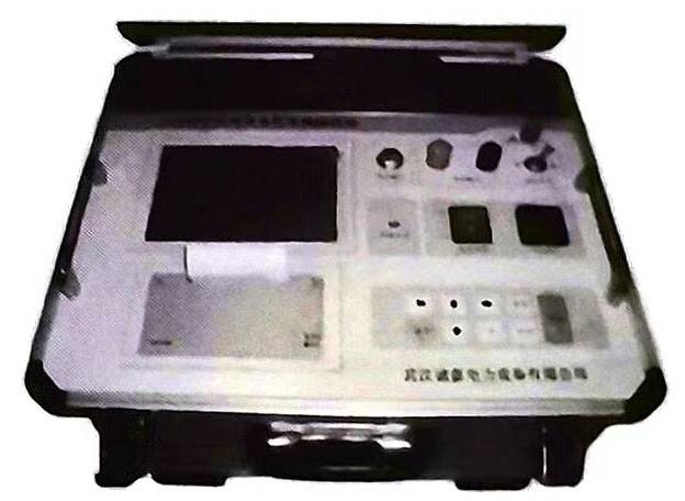
Figure 4 Capacitance bridge tester
Test method (as shown in Figure 5):
1) Before testing, insert the red and black test wire holes of the digital capacitance meter into the test wires, turn on the capacitance meter, and select the appropriate gear;
2) Immediately after step 1, adjust the capacitance meter to zero, and return the capacitance meter value to zero by rotating the black button;
3) Before testing the capacitance, use a short-circuit wire with an insulating sheath to briefly short-circuit the two lead wires of the capacitor to discharge;
4) Connect the other ends of the two test pens to the two leads of the capacitor (generally use a clip to clamp the lead position, and it is strictly forbidden to pinch the lead wire with your hands for testing), and the value after stabilization is the capacitance value.
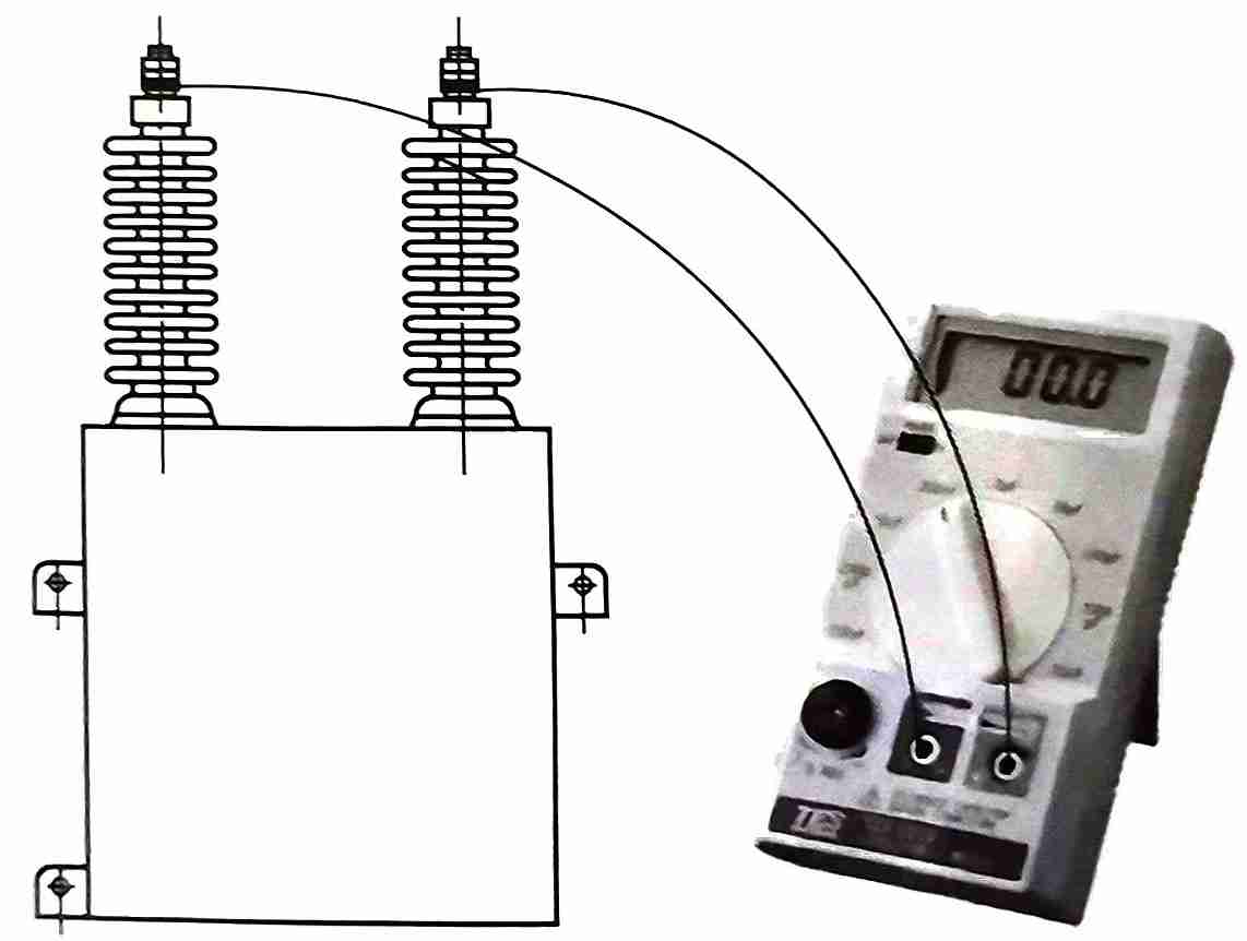
Figure 5 Schematic diagram of capacitor capacitance measurement by capacitance meter
This method is convenient and simple to test the capacitance value. It does not require an external power supply. The disadvantage is that the capacitor needs to be short-circuited and discharged before testing. When testing on the capacitor tower of the DC converter station, some leads need to be removed (although the capacitor bridge can test the capacitor tower capacitance without removing the leads, in fact, it is more convenient to use a digital capacitance meter on the capacitor tower in the converter station by removing a small amount of wires).
The relevant regulations for AC and DC filters and parallel capacitors in converter stations stipulate that the initial value difference of the capacitance of a single capacitor should not exceed -5%~10%, otherwise it should be replaced. Sometimes, stricter standards can be adopted according to actual conditions.
(3) AC withstand voltage test. The purpose of the AC withstand voltage test is to check whether there are defects in the main insulation of the capacitor device test and to verify its ability to withstand short-term overvoltage. The capacitor withstand voltage test can be divided into an inter-electrode withstand voltage test and a two-electrode-to-shell withstand voltage test.
The AC withstand voltage test is a destructive test. The capacitor capacitance needs to be measured before and after the AC withstand voltage test, and the difference before and after should be within the specified range. Inter-pole AC withstand voltage, the insulation margin between the two poles of the capacitor is very small. Due to the manufacturing differences of the insulating medium and the uneven distribution of the electric field, the withstand voltage test may cause damage or local damage to individual dielectrics with insulation weaknesses, leaving hidden dangers for the future operation of the equipment. Therefore, the inter-pole withstand voltage test is basically not performed. For the withstand voltage test of the pole to the shell, the two poles must be short-circuited and pressurized. This test can effectively find defects such as internal moisture, porcelain bushing damage, and mechanical damage. The insulation margin of the capacitor pole to the shell is large. Generally, this test is only performed during the handover test or when there is a problem with the capacitor batch on site. Routine tests of normal converter station filters and parallel capacitor devices are not required. The following only introduces the AC withstand voltage test of the pole to the shell.
AC withstand voltage test of the pole to the shell:
Test method: Add a certain power frequency voltage as required to meet the withstand voltage requirements within a certain period of time. The capacitor device test standard is shown in Table 4-2. When the product factory test voltage value does not meet the requirements of Table 4-2, the handover test voltage should be 75% of the factory test voltage value.

(4) Impact closing test. After the completion of infrastructure installation and before the formal operation and commissioning of the AC filter and shunt capacitor device, the AC filter and shunt capacitor device shall be subjected to impact closing test 3 times at the rated voltage of the grid. All kinds of protection shall not be activated; and the ratio of the maximum value to the minimum value of the capacitance of each phase in the capacitor group shall not exceed 1.08 (for this item, in the actual converter station impact closing test, generally after the test is completed, the capacitance measurement is no longer performed. As long as the unbalanced current of the three-phase capacitor tower does not exceed 25% of the I-stage alarm value in the third impact closing test, the test is considered to have passed).
1.2 Handover test of resistors
The main function of resistors in filters and shunt capacitor devices is to dissipate heat. As supporting equipment for filters and shunt capacitor devices, the handover test of resistors is mainly to measure the resistance value of resistors to check whether the resistors are short-circuited, poorly contacted or open-circuited.
When measuring the resistance value of resistors, the resistors need to be restored to normal temperature for testing. The initial value difference at the same temperature should not exceed ±3%. When the temperature difference is large, it should be corrected to the same temperature for comparison.
1.3 Acceptance test of reactor
The acceptance test of reactors in filters and parallel capacitor devices mainly includes inductance test and coil resistance test, which are used to detect whether the coil is faulty. Inductance test method: apply power frequency voltage to the lead terminal of the reactor through the voltage regulator, monitor the voltage and current with a voltmeter and an ammeter, gradually increase the voltage until the current reaches 1A, read the voltage value U, and the inductance value L=U/(100π). The initial value difference of inductance should not exceed ±3%. When measuring the DC resistance of the coil, the measurement uncertainty of the instrument should be less than 1%. At the same temperature, the initial value difference of the DC resistance of the coil should not exceed ±3%. When the temperature difference is large, it should be corrected to the same temperature for comparison.
1.4 Acceptance test of metal zinc oxide lightning arrester in the filter
There is no essential difference between the acceptance test of metal zinc oxide lightning arrester in the AC and DC filter field of the converter station and the metal zinc oxide lightning arrester in the ordinary AC substation.
(1) Measure the insulation resistance of the metal zinc oxide arrester and the base: For the internal rated voltage level of the filter and parallel capacitor, the arrester above 35kV uses a 5000V insulation resistance meter, and the insulation resistance is not less than 2500MΩ; the arrester of 35kV and below uses a 2500V insulation resistance meter, and the insulation resistance is not less than 1000MΩ; the base insulation resistance is measured with a 2500V insulation resistance meter, and the insulation resistance is not less than 100MΩ.
(2) Test the metal zinc oxide arrester with a DC reference voltage of 1mA and a leakage current test at 0.75 times the DC reference voltage: The metal zinc oxide arrester can be tested in sections or as a whole. The difference between the measured reference voltage and the initial value should not exceed ±5%, and the DC leakage current at 0.75 times the reference voltage should not exceed 50μA or the difference from the initial value should not exceed 30%.
(3) Check the function of the arrester discharge counter, and the counter should operate reliably.
(4) Continuous current in operation: Since the AC and DC filters and shunt capacitors are all equipped with fixed metal fences, and the lightning arresters are all inside the fences, as supporting equipment for the filter and shunt capacitor devices in the converter station, this test item is generally not performed.
1.5 Acceptance test of current transformers (including photocurrent transformers) in filter and shunt capacitor devices
At present, according to different converter stations, the current transformers in filter and shunt capacitor devices mainly include oil-immersed current transformers, gas-filled current transformers, silicone rubber current transformers, epoxy resin current transformers, and photocurrent transformers. The following introduces their acceptance test items respectively.
(1) Oil-immersed current transformer.
1) Analysis of dissolved gas in oil (currently, this test is generally not performed during acceptance).
2) Insulation resistance test: Measure the insulation resistance of the primary winding to the secondary winding and the casing, between each secondary winding and to the casing, and the insulation resistance of the end screen to the ground. The insulation resistance measurement should use a 2500V insulation resistance meter. The insulation resistance of the primary winding to the secondary winding and the shell should be greater than 3000MΩ, and the insulation resistance between the secondary windings and the shell should be greater than 1000MΩ. The insulation resistance of the end screen to the ground should not be less than 1000MΩ. If it is less than this value, the dielectric loss test of the end screen should also be carried out.
3) Capacitance and dielectric loss factor: Generally, the capacitance and dielectric loss factor are measured by the primary equipment disconnection positive connection method. The initial value difference of capacitance is not more than ±5%, and the initial value difference of dielectric loss value is not more than 0.8%.
4) Measure the DC resistance of the primary winding.
5) A-V characteristic test of oil-immersed current transformer.
6) Transformation ratio test of oil-immersed current transformer.
7) AC withstand voltage test of oil-immersed current transformer, the primary winding test voltage is 80% of the factory value, and the test voltage between the secondary windings and to the ground is 2kV.
8) Wiring group and polarity inspection.
9) Partial discharge test (this test is not usually performed on site).
(2) Gas-filled current transformer (usually SF6 gas).
1) SF6 gas micro-water test.
2) Insulation resistance test: measure the insulation resistance of the primary winding to the secondary winding and the casing, between each secondary winding and to the casing. A 2500V insulation resistance meter should be used for insulation resistance measurement. The insulation resistance of the primary winding to the secondary winding and the casing should be greater than 3000MΩ, and the insulation resistance between the secondary windings and to the casing should be greater than 1000MΩ.
3) Measure the DC resistance of the primary winding.
4) Current transformer A-V characteristic test.
5) Current transformer ratio test.
6) Current transformer AC withstand voltage test, the primary winding test voltage is 80% of the factory value, and the test voltage between the secondary windings and to the ground is 2kV.
7) Wiring group and polarity inspection.
8) Partial discharge test (this test is not usually performed on site)
9) SF6 gas sealing test.
10) SF6 density meter calibration.
During the test of the filter and parallel capacitor device, the capacitor device test is one of the important links to ensure the safe and reliable operation of the device. Through the handover test of the capacitor, lightning arrester and current transformer, the performance of the capacitor device and the stability of the overall operation of the system can be ensured.
(3) Silicone rubber and epoxy resin current transformers.
1) Insulation resistance test: Measure the insulation resistance of the primary winding to the secondary winding and the shell, and between each secondary winding and to the shell. A 2500V insulation resistance meter should be used for insulation resistance measurement. The insulation resistance of the primary winding to the secondary winding and the shell should be greater than 3000MΩ, and the insulation resistance between the secondary windings and to the shell should be greater than 1000MΩ.
2) Measure the DC resistance of the primary winding.
3) Current transformer A-V characteristic test.
4) Current transformer ratio test.
5) Current transformer AC withstand voltage test, the primary winding test voltage is 80% of the factory value, and the test voltage between the secondary windings and to the ground is 2kV.
6) Wiring group and polarity check.
7) Partial discharge test (this test is generally not performed on site).
(4) Photocurrent transformer.
1) Transformation ratio test.
2) Primary current loop resistance test.
3) Laser power test (this test is performed when online monitoring shows that the optical power is abnormal).
2 Capacitor device test of filter and parallel capacitor device Routine test items
(1) For the filter and parallel capacitor device in the converter station, the capacitance measurement of a single capacitor should be included in the routine test items during the first power outage test after the new equipment is put into operation. The test results of this test should be compared with the test results of the handover test. If most of the test values are basically unchanged from the handover test, the capacitance test of a single capacitor may not be performed in the subsequent routine power outage inspection and maintenance if there are no abnormal defects in the entire device.
(2) Capacitor bridge arm capacitance measurement: Use a digital capacitance meter or capacitance bridge with an uncertainty of no more than 1% to measure the entire group, and the capacitance of the capacitor group must not differ from its initial value by more than ±2%.
(3) Resistor DC resistance measurement: Before measurement, wait for the resistor to return to room temperature. A bridge or digital ohmmeter can be used for measurement, and the measurement uncertainty of the instrument must not exceed 0.5%. At the same temperature, the initial value difference should not exceed ±3%. When the temperature difference is large, it should be corrected to the same temperature for comparison.
(4) Measurement of reactor inductance and coil DC resistance: When measuring reactor inductance, the measurement uncertainty of the instrument is required to be no more than 0.5%. It is recommended to calculate the inductance by applying power frequency voltage and measuring power frequency current. When measuring, apply power frequency voltage to the lead terminals of the reactor through the voltage regulator, monitor the voltage and current with a voltmeter and ammeter, gradually increase the voltage until the current reaches 1A, read the voltage value U, and the inductance value L=U/(100π). When measuring the DC resistance of the coil, the measurement uncertainty of the instrument should be less than 1%, and the difference in the initial value of the DC resistance of the coil should not exceed ±3% at the same temperature. When the temperature difference is large, it should be corrected to the same temperature for comparison.
In the capacitor device test, these routine tests can ensure the performance and long-term stable operation of the filter, parallel capacitors and other electrical devices. Through regular inspection and adjustment, potential problems can be discovered in time to ensure the safety and reliability of the system.
3 Diagnostic test items
3.1 Capacitance measurement of single capacitor
The capacitance value of a single capacitor needs to be measured if any of the following situations occurs:
(1) The capacitance test result of the capacitor group (arm) exceeds ±2%.
(2) There is an opportunity for maintenance test, and before the filter is shut down, the unbalanced current exceeds the protection alarm value of 50%.
(3) The unbalanced current exceeds the protection action value during operation, and the protection trips and causes the filter to shut down.
3.2 Capacitance measurement requirements of a single capacitor
Measure with a digital capacitance meter with an uncertainty of no more than 1%. It is not necessary to disconnect the connecting wires in the capacitor group during measurement. If the initial value difference of the capacitance of a single capacitor exceeds -5%~10%, it should be replaced. The capacitance difference between the new capacitor and the replaced capacitor should be within 1% (refer to the nameplate value or routine test value). After replacing the capacitor, measure the equivalent capacitance of the capacitor group, and the difference from the rated value or initial value should not exceed ±2%, and the unbalanced current should be less than the protection alarm value of 20%.
The diagnostic test items performed in the capacitor device test can help evaluate the operating status and performance of the capacitor, ensure timely detection and resolution of problems in the event of a fault or abnormal capacitance, and thus improve the reliability and operating efficiency of the system.

