1 Overview of basic knowledge of capacitor
1.1 Basic Knowledge of Capacitor: Understanding Capacitance and Its Units
What is capacitance? As the name implies, it is the ability to hold electricity. “General Physics” says: “For any ‘isolated’ conductor that is not affected by the outside world, when the conductor is charged, the ratio C of the charge q carried by the conductor to the corresponding potential U is a physical quantity that is independent of the charge carried by the conductor and is called the capacitance of the ‘isolated’ conductor.” This is an important part of the basic knowledge of capacitor. That is,
![]() (1)
(1)
The capacitance of a conductor represents the unique properties of the conductor, and its value is equal to the charge carried by the conductor when the potential of the conductor is one unit.
In the International System of Units, the unit of capacitance is farad. If the charge carried by the conductor is 1C and the corresponding potential is 1V, the capacitance of the conductor is 1 farad, which can be represented by the capital letter F. If the unit of Farad is too large, it can also be expressed in smaller units such as mF, μF, nF, pF, etc. Their relationship is as follows:
![]() (2)
(2)
![]() (3)
(3)
![]() (4)
(4)
![]() (5)
(5)
The dimension of capacitance is: I2L-2M-1T4.
1.2 What is a capacitor?
It is mentioned in the basic knowledge of capacitors that capacitors are devices that hold electric charge. When there are other objects around a conductor, the capacitance of the conductor will be affected. Therefore, it is necessary to design a conductor combination with a large capacitance value, but not too large geometric size, and of course not affected by other objects. Such a conductor combination is a capacitor. In physics, the concept of a capacitor can be expressed as: “a conductor system composed of two conductors when there is no other charged conductor around”. The capacitance (or capacitance) of a capacitor is defined as: when the two plates of the capacitor carry equal and opposite charges q, the ratio of the charge q to the corresponding potential difference UA—UB between the two plates, that is,
![]() (6)
(6)
In fact, an isolated conductor can still be considered as a capacitor, but the other conductor is at infinity and has a zero potential. Equation (6) becomes equation (1). Therefore, it can be seen that the capacitance of the so-called “isolated conductor” is actually still the capacitance between the two conductors. The difference from the general capacitance is that the other conductor is at infinity. But capacitance is a property between conductors after all. The capacitance of an isolated conductor does not actually exist.
2 Physical properties
2.1 Physical meaning of capacitors
The most basic physical properties of capacitors can be expressed by equation (6), that is, the relationship between capacitance, charge, and potential difference (voltage). From this relationship and the relationship between charge and current, we can also get the most commonly used relationship between voltage and current on a capacitor in circuits and electronics, that is,
![]() (7)
(7)
When the current is changing, equation (7) should be written as
![]() (8)
(8)
In general applications, the potential difference between the two plates of a capacitor becomes the voltage on the capacitor, represented by Vc. Thus, equations (7) and (8) give the relationship between the voltage and current of a capacitor:
![]() (9)
(9)
The energy storage of a capacitor is
![]() (10)
(10)
The unit is joule. This is the formula that usually represents the energy storage of a capacitor.
2.2 Capacitance of a flat plate capacitor
![]() (11)
(11)
Where S is the plate area of the capacitor; d is the distance between the plates; Ɛ0 is the dielectric constant of a vacuum; Ɛ is the dielectric constant of the medium between the plates relative to a vacuum. Ɛ0 is:
![]() (12)
(12)
From formula (11), we can get: the capacitance of a flat plate capacitor is proportional to the plate area and inversely proportional to the distance between the plates, and proportional to the dielectric constant of the medium relative to vacuum. Therefore, in order to obtain a large capacitance, the largest possible plate area, the smallest possible plate distance and the largest possible dielectric constant of the medium between the plates should be selected. This is one of the criteria for manufacturing capacitors. These criteria in the basic knowledge of capacitor provide an important basis for the design and manufacture of capacitors.
3 Dielectric
3.1 Relative dielectric constant of dielectric
In physics experiments, it can be found that the electric field force between the two capacitor plates that are open to the outside world and charged becomes smaller after a dielectric is inserted between the two plates. This phenomenon shows that the potential between the two plates of the capacitor inserted with the dielectric decreases. From formula (1), we know that under the condition that the charge of the capacitor remains unchanged, the result of the decrease in voltage between the capacitor plates must be an increase in capacitance. From this, we can know that inserting a dielectric between the capacitor plates can increase the capacitance. To increase the capacitance, a dielectric with a relatively large relative dielectric constant is usually added between the capacitor plates.
3.2 Dielectric loss
Under an applied voltage, a part of the electrical energy in the dielectric is converted into heat energy, which is called dielectric loss. Generally speaking, dielectrics have weak conductivity, and the energy loss caused by leakage current is small. The main dielectric loss occurs in the process of repeated polarization of the dielectric by the high-frequency external electric field under the action of high-frequency alternating voltage. The higher the frequency, the more significant the heat. If the heat is intense, the dielectric will lose its insulation properties and cause damage. The basic knowledge of capacitor explains the dielectric loss phenomenon in detail, which is the key to understanding the performance of capacitors
3.3 Dielectric breakdown
In a strong electric field, the dielectric will lose its polarization characteristics and become a conductor, which will eventually lead to dielectric damage (such as lattice cracks, oxidation, melting, etc.). This phenomenon is called dielectric breakdown. There are three forms of dielectric breakdown, namely thermal breakdown, chemical breakdown and electrical breakdown.
Thermal breakdown is caused by the loss of dielectric. When the heat generated by the loss is greater than the heat transferred by the dielectric to the surrounding, the temperature of the dielectric rises rapidly, the conductivity increases accordingly, and even causes thermal damage to the dielectric. Therefore, thermal breakdown always occurs in the worst place of the capacitor.
Chemical breakdown occurs after the dielectric has been working under high voltage for a long time. Strong electric fields will cause local air collision ionization near the small holes on the surface or inside of the dielectric, thereby causing corona of the dielectric and generating ozone and carbon dioxide. These gases are harmful to organic insulating materials, which will reduce the insulation performance of these materials and damage the dielectric.
Electrical breakdown is caused by the free electrons excited by the dielectric under the action of a strong electric field. At this time, the electron current in the dielectric increases sharply with the increase of the electric field, thereby destroying the insulation performance of the dielectric.
3.4 Dielectric breakdown field strength
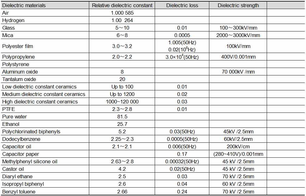
The relative dielectric constant, dielectric loss and dielectric strength of commonly used dielectrics for capacitors are shown in Table 1.
Table 1 Relative dielectric constant, dielectric loss and dielectric strength of commonly used dielectrics for capacitors
3.5 Dielectric absorption (relaxation time) and residual voltage
If there is no dielectric absorption in the capacitor, the initial charging or polarization current when connected to a DC power supply will be
![]() (13)
(13)
Where i is the polarization current of the capacitor; V is the applied voltage; R is the resistance of the capacitor in series; e is the base of the natural logarithm (2.718); C is the capacitance of the capacitor; t is time.
When time t tends to infinity, the polarization current tends to zero. If the R value is small, this process will be completed in a very short time and the capacitor will be fully charged. However, in fact, for solid dielectric capacitors, if a fully charged capacitor is discharged instantaneously and then opened, after a period of time, some of the original charge will be absorbed by the dielectric, and new charge will of course accumulate “on the capacitor plates”, which will produce a dielectric absorption effect. The corresponding voltage generated by the capacitor is called residual voltage. For liquid electrodes or dielectrics, the residual voltage is caused by internal resistance, which is not just ESR, but the parasitic resistance deep inside the rough electrode. This internal resistance is usually not testable outside the capacitor.
4 Basic knowledge of capacitor and characteristics
4.1 Relationship between various parameters of capacitors
The relationship between the current and voltage of a capacitor in the time domain is
![]() (14)
(14)
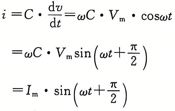
Under the excitation of the sinusoidal voltage Vm sinωt, the current in the capacitor is
 (15)
(15)
It can be seen that under the excitation of the sinusoidal voltage, the current on the capacitor leads the voltage by π/2 radians, that is, 90°; similarly, by eliminating sin(ωt+2/π) in the second and third rows of equation (15), we get ωC·Vm=Im, after sorting, it is
![]() (16)
(16)
Thus, the ratio of the current peak (or effective value) to the voltage peak (or effective value) in the capacitor is
![]() (17)
(17)
Wherein, Xc has the same dimension as the resistance, and thus becomes the reactance of the capacitor, referred to as capacitive reactance. Obviously, the higher the frequency, the smaller the capacitive reactance; similarly, the larger the capacitance, the smaller the capacitive reactance. The relationship in formula (17) also shows the role of the capacitor in filtering, bypassing, isolating DC and coupling AC signals at the same time.
In the complex frequency domain (S domain), the relationship between the various parameters of the capacitor is
![]() (18)
(18)
4.2 Capacitor connection
Capacitance of parallel capacitors:
![]() (19)
(19)
Like the series characteristics of resistors, the capacitive reactance of parallel capacitors is
![]() (20)
(20)
Capacitance of series capacitors:
![]() (21)
(21)
Like the parallel characteristics of resistors, the capacitive reactance of series capacitors is
![]() (22)
(22)
4.3 Main functions of capacitors
The main functions of capacitors: energy storage, filtering, coupling (DC isolation), bypass (decoupling, called decoupling decades ago), resonance, phase shifting, and holding (used in sample-hold circuits and integration circuits).
In summary, the above content involves the key content of the basic knowledge of capacitor, and comprehensively explains its parameter relationship, connection method and application characteristics.

