1.Key parameters ofkey performance of capacitor
The key parameters of key performance of capacitor are the basic basis for selecting and using capacitors. The main parameters of capacitors are as follows
1.1 Rated voltage and dielectric strength
The voltage that can be continuously applied across the capacitor is one of its important key performances. Generally, capacitors are DC voltage, while those dedicated to AC are AC effective voltage. The rated voltage of a capacitor is lower than the dielectric strength (breakdown voltage) of the medium in the capacitor. The difference between the breakdown voltage and the rated voltage of the capacitor varies with the manufacturing process. For example, the aluminum oxide medium of an electrolytic capacitor can be controlled very accurately, so the general breakdown voltage is 1.1~1.3 times the rated voltage; other media are usually 1.75~2 times or more; capacitors used to suppress electromagnetic interference of power supplies require a higher ratio to ensure electrical safety.
1.2 Capacitance
The capacitance of a capacitor is another important key performance of capacitor, which is determined by the impedance presented when measuring AC capacitance. Usually, the capacitance of AC changes with the frequency, voltage and measurement method, but the degree of change of capacitors of different specifications is different. Unless the capacitance is required to be particularly precise and the temperature characteristics are particularly stable, the capacitance of the general capacitor changes with frequency less than the tolerance accuracy of the capacitance.
Like frequency, the temperature during measurement has a certain influence on the capacitance of the capacitor. As the measurement temperature decreases, the capacitance will change accordingly
1.3 Capacitance error
During the manufacturing process of capacitors, it is impossible to ensure that the capacitance of each capacitor is completely consistent with the design value (or nominal value). There is always a certain deviation, that is, the capacitance error (tolerance) of the capacitor. The capacitance error of capacitors is mostly expressed as a percentage. The capacitance error of most capacitors is J-grade: ±5%; K-grade: ±10%; M-grade: ±20%; S-grade: ±50%/-20%; Z-grade: ±80%/-20%.
1.4 Loss factor
The loss caused by leakage current, dielectric absorption, equivalent series resistance, etc. is related to the operating frequency. For dielectric absorption, as long as the loss is low, the change in its dielectric coefficient can usually be ignored. The polarization process of the dielectric under the electric field causes the collision between molecules and consumes energy, thus generating losses, which also causes the dielectric constant to decrease. In electrolytic capacitors, the equivalent series resistance is the main cause of loss, while the losses caused by leakage current and dielectric absorption can be ignored. Therefore, the dissipation factor of the electrolytic capacitor is expressed as the ratio of the series equivalent resistance ESR to the capacitive reactance 1/ωC, sometimes also called the loss tangent (tanδ). Therefore, the loss tangent (tanδ) of the electrolytic capacitor increases with frequency.
The loss factor indicates the magnitude of the capacitor’s own loss when it is working. The magnitude of this loss can be defined as: when the capacitor is applied with alternating current, the ratio of the loss generated by the capacitor in each cycle to the power stored in the capacitor in each cycle, that is,
The power consumed in each cycle is the loss factor-the power stored in each cycle
![]() (1)
(1)
This is the most basic definition of the capacitor’s loss factor.
This expression is the same as the power factor in electrical engineering, so some literature translates the loss factor into power factor, but the meanings of the two are different. It is better to express it as loss factor here.
1.5 Equivalent series resistance
The resistance from the capacitor electrode to the lead end. Generally, the equivalent series resistance (ESR) of foil capacitors is smaller than that of metallized capacitors, the ESR of bimetallized and heavy metallized capacitors is smaller than that of general metallized capacitors, the ESR of multi-leads is smaller than that of single-leads, and the ESR of flat electrode plates is smaller than that of rough electrode plates, etc.
1.6 Temperature coefficient
The temperature coefficient (temperature characteristics) is the degree to which capacitance changes with temperature. The dielectric constant of some media increases with increasing temperature. Most media belong to this category, and their variation range is usually smaller than the tolerance range; some media decrease with increasing temperature, such as polypropylene; some media may have different changes in different temperature ranges, such as industrial ceramic capacitors.
1.7 Operating temperature range
Any medium has an operating temperature range (operation temperature). Excessively high temperature will cause changes in the physical properties of the medium (such as melting, decreased dielectric strength) and chemical changes (such as carbonization) and no longer meet the requirements of capacitor dielectric performance; electrolytic capacitors must avoid evaporation of the electrolyte and cause permanent damage to the capacitor. Therefore, one of the key performance of capacitor is its stability and reliability at different operating temperatures.
1.8 Leakage current
The leakage current of the capacitor is mainly caused by the fact that the insulation resistance of the medium is not infinite and the defects (impurities) in the medium. Different mediums have different leakage currents. For example, the leakage current of aluminum electrolytic capacitors is mainly caused by the damage to the aluminum oxide medium caused by the presence of chlorine, iron, and copper ions, as well as the micro-galvanic cell effect.
1.9 Lifespan
In theory, most capacitors do not have a lifespan (1ife test) problem. Only liquid medium (electrode) or medium has a lifespan problem when the dielectric coefficient decreases after voltage is applied. The most obvious is the aluminum electrolytic capacitor. Since the negative electrode of the aluminum electrolytic capacitor is the electrolyte, when the electrolyte dries up, the negative electrode area of the aluminum electrolytic capacitor is greatly reduced, which greatly reduces the capacitance. When the capacitance drops to the end-of-life value, the aluminum electrolytic capacitor is declared to have reached the end of its life. Usually, aluminum electrolytic capacitors are marked with the maximum operating temperature and the service life at this temperature, such as 105℃/2000h.
2 Parameter representation of key performance of capacitor
2.1 Classification of capacitors
According to the dielectric classification, capacitors can be divided into: air dielectric capacitors, mica capacitors, paper dielectric capacitors, organic film capacitors [organic films mainly include: polyester film (formerly known as polyester), polypropylene film, polycarbonate film, polytetrafluoroethylene film, etc.], ceramic dielectric capacitors, electrolyte capacitors (aluminum electrolytic capacitors, tantalum electrolytic capacitors), ferroelectric capacitors and double-layer capacitors (supercapacitors), etc. The classification of capacitors directly affects their key performance, such as stability, withstand voltage and temperature adaptability.
2.2 Nominal capacitance value and accuracy of capacitors
The nominal capacitance value of capacitors is usually divided into E6 series, E12 series and E24 series, as shown in Table 1.
Table 1 Preferred values of E6 series, E12 series and E24 series

2.3 Representation of capacitance
(1) Marking method of small capacitors
Small-capacitance capacitors are mostly marked in picofarads. The number shown is the capacitance, and there is no unit (PF) after the number. For example, 8 means the capacitance is 8PF (0.000 008μF); for another example: 100 means the capacitance is 100PF (0.0001μF). Capacitance is one of the basic parameters for evaluating the key performance of capacitor.
(2) Marking method of small and medium-capacitance capacitors
Small and medium-capacitance capacitors can be represented in nanofarads (nF or n) or microfarads (μF). When nF is expressed, n is added after the digit to indicate the capacity, for example: 100n indicates 100nF (0.1 μF), and 4n7 indicates 4.7nF (0.0047μF); when μF is expressed, μF is not indicated after the digit, for example, 0.01 indicates 0.01μF; and 0.47 indicates 0.47μF.
(3) Capacitance with digital symbols
The unit of capacitance with digital symbols is picofarad (PF), for example, 101 indicates 100PF (0.0001μF); 683 indicates 68,000PF (0.068μF); and 475 indicates 4,700,000PF (4.7μF); tantalum electrolytic capacitors also use this method of expression, such as 476 indicates 47μF.
(4) Color code marking method for capacitors
The same as the marking method of color ring resistors, the unit of capacitance represented is picofarad.
(5) Marking of electrolytic capacitors
The capacitance of electrolytic capacitors is relatively large, and is expressed in microfarads (μF). Usually, the number is followed by μF or μ, such as 0.22μ, 4.7u, 22μ, 470μ, 3300μ, 10 000μ, 47 000μ, etc.
(6) Marking of supercapacitors
The capacitance of supercapacitors is particularly large, and is often expressed in farads (F), such as 0.1F, 5F, 47F, 100F, 3300F5000F. One of the key performance of capacitor characteristic is their large capacitance characteristics, which are suitable for applications that require large energy storage.
2.4 Capacitance error
The capacitance error of capacitors is usually expressed by characters:
The first type, absolute error, is usually expressed in the absolute error of the capacitance value, with PF as the unit, that is: B represents ±0.1PF, C represents ±0.25PF, D represents ±0.5PF, Y represents ±1PF, A represents ±1.5PF, and V represents ±5PF. This expression is usually used for small-capacity capacitors.
The second type, relative error, is expressed as a percentage of the deviation of the nominal capacitance value, namely: D represents ±0.5%, P represents ±0.625%, F represents ±1%, R represents ±1.25%, G represents ±2%, U represents ±3.5%, represents ±5%, K represents ±10%, M represents ±20%, S represents ±50%/-20%, represents ±80%/-20%.
Among them, those with a capacitance error of less than 5% can be called precision capacitors, while general capacitors are mostly J, K, and M grades. For class II ceramic capacitors, they are mostly K and M grades, and electrolytic capacitors are mostly M and S grades, which are mostly used in occasions where capacitance accuracy is not required. The accuracy of capacitance error is an important criterion for evaluating the key performance of capacitor.
2.5 Rated working voltage of capacitors
According to the provisions of national standard GB2472-81, the rated voltage sequence of capacitors is shown in Table 2.
Table 2 Rated working voltage sequence of capacitors

2.6 Representation of rated voltage of capacitors
(1) Direct voltage marking
Same as voltage sequence marking.
(2) Letter symbols
The voltage (DC voltage) codes of capacitors produced by Japanese manufacturers are: 0E for 2.5V, 0J for 6.3V, 1A for 10V, 1B for 12V, 1C for 16V, 1E for 25V, 1V for 35V, 1H for 50V, 1J for 63V, 1K for 80V, 2A for 100V, 2C for 160V, 2D for 200V, 2E for 250V, 2G for 400V, 2W for 450V, 2H for 500V, 2J for 630V, 2K for 800V, 3A for 1kV, 3D for 2kV, 3F for 3kV, 3C for 4kV, 3H for 5kV, 3J for 6kV, 3K for 8kV, 4A for 10kV, 4B for 12kV, and 4C for 15kV. Similarly, 3E is the rated voltage of 2500V. It can also be seen that A, B, C, D, E, F, G, H, J, K, W represent 1.0, 1.2, 1.62.0, 2.5, 3.0 (3.15), 4.0, 5.0, 6.3 (6.0), 8.0, 4.5 respectively. Numbers before the characters: 0 represents 10°, 1 represents 101, 2 represents 102, 3 represents 103, 4 represents 104, and so on; AC voltage: E2 represents 250V, GB represents 250V of X2 of the power supply electromagnetic interference suppression capacitor, GC represents 250V of X1 and Y2 of the power supply electromagnetic interference suppression capacitor, and GD represents 250V of Y3 of the power supply electromagnetic interference suppression capacitor.
2.7 Temperature characteristics
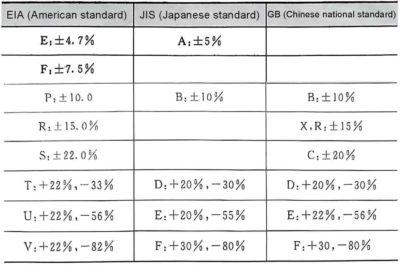
Temperature characteristics mainly refer to the degree of change of capacitance with temperature, and are also one of the key parameters of capacitors. Most capacitor products in the United States and China indicate their temperature coefficients, and each country has formulated corresponding standards, see Table 3 to Table 6.
Table 3 Representation of temperature characteristics of Chinese national standards
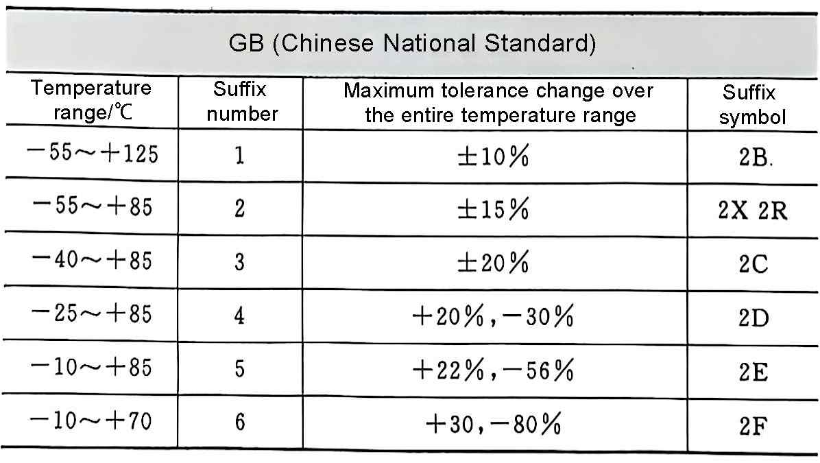
Table 4 Representation of temperature characteristics of American standards
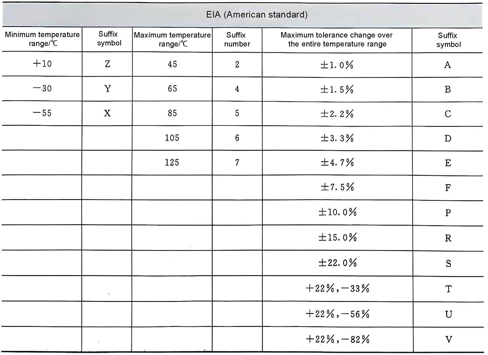
Table 5 Representation of temperature characteristics of Japanese standards
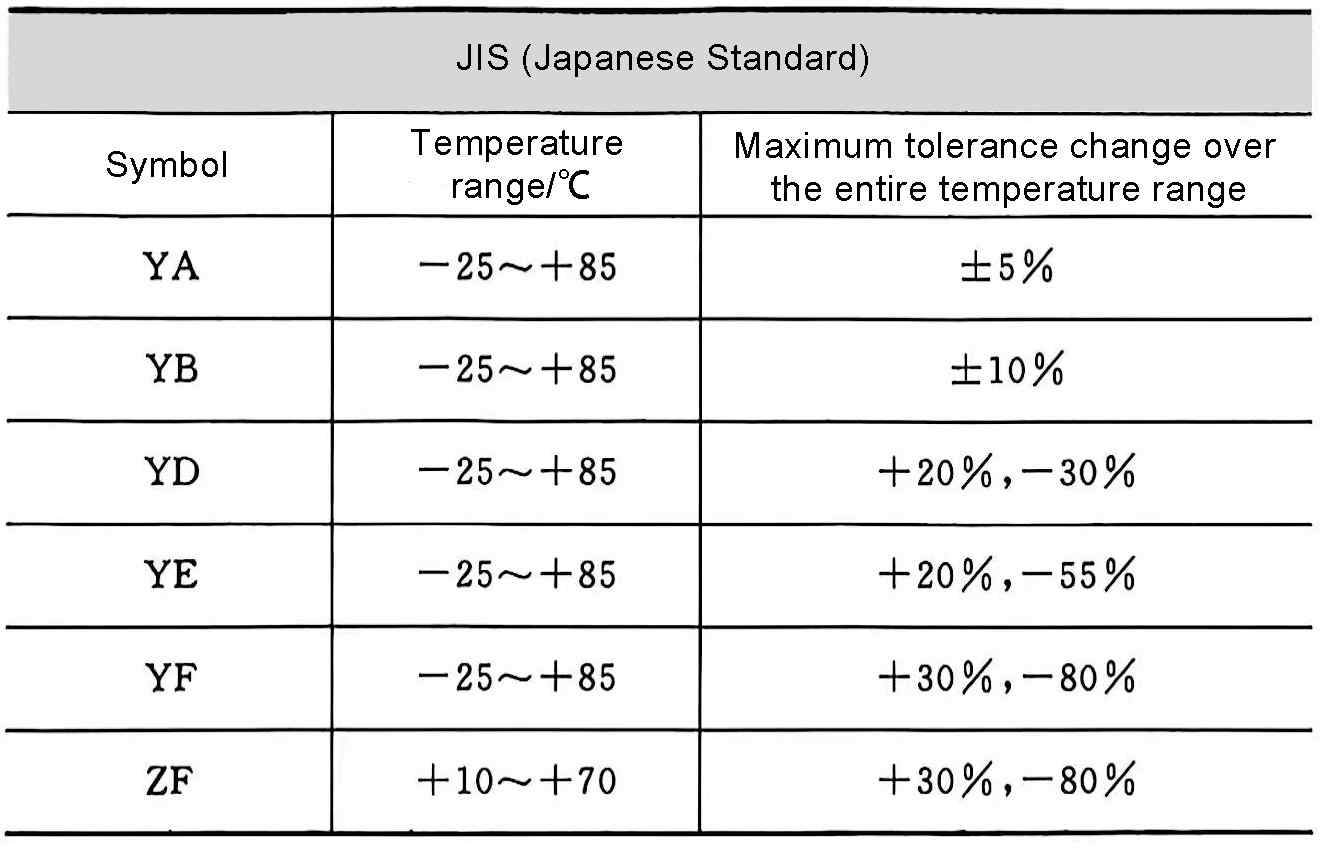
Table 6 Comparison of temperature characteristics standards in China, the United States, and Japan
For example, the most common ceramic dielectrics are X7P and Z5U, where X7P is the American standard, where X represents the minimum operating temperature of -55℃, 7 represents the maximum operating temperature of +125℃, and the maximum tolerance range in the entire operating temperature range is ±10%; similarly, Z5U is also the American standard, where Z represents the minimum operating temperature of +10℃, 5 represents the maximum operating temperature of +85℃, and the maximum tolerance range in the entire operating temperature range is +22% and -56%. Therefore, the temperature coefficient of X7P is: the entire operating temperature range is -55~+125℃, and the tolerance range is ±10%. The temperature coefficient of Z5U is: the entire operating temperature range is +10~+85℃, and the tolerance range is +22% and -56%.
3 Naming of domestic capacitors
The model of domestic capacitors is generally composed of four T parts (not applicable to varistor, variable, and vacuum capacitors). They represent the device type, dielectric type, classification, and product serial number in turn, see Table 7.
Table 7 Method of indicating capacitor models in my country

In the national standard GB2420-81 “Naming method of resistor and capacitor models for electronic equipment”, it is specially noted that when B represents non-polar organic films other than polystyrene, a letter is added after B to distinguish the specific material. For example, polytetrafluoroethylene is represented by BF, polypropylene is represented by BB, and so on. The letters that distinguish specific materials are determined by the model management department.
For example, aluminum electrolytic capacitors are represented by CD, tantalum electrolytic capacitors are represented by CA, those with CH mark are composite dielectric capacitors, CC series are high-frequency ceramic dielectric capacitors, CBB are polypropylene capacitors, and so on.

