Power capacitors are the most important equipment in the AC and DC filters and shunt capacitor devices of DC converter stations. Understanding and mastering the production process of capacitors is of certain practical significance for us to better maintain the equipment and handle faults during equipment operation.
1.Overview of power capacitors
Capacitors have strict production processes in equipment manufacturers, and the environmental cleanliness is strictly controlled during the production process. Process control is crucial to ensuring the quality of capacitors. Strict processes are the basis of capacitor production and manufacturing. They run through the entire process of capacitor production and are an important means to achieve product design and ensure product quality under certain production conditions. As shown in Figure 1, this is the general process flow of capacitor production in the workshop.
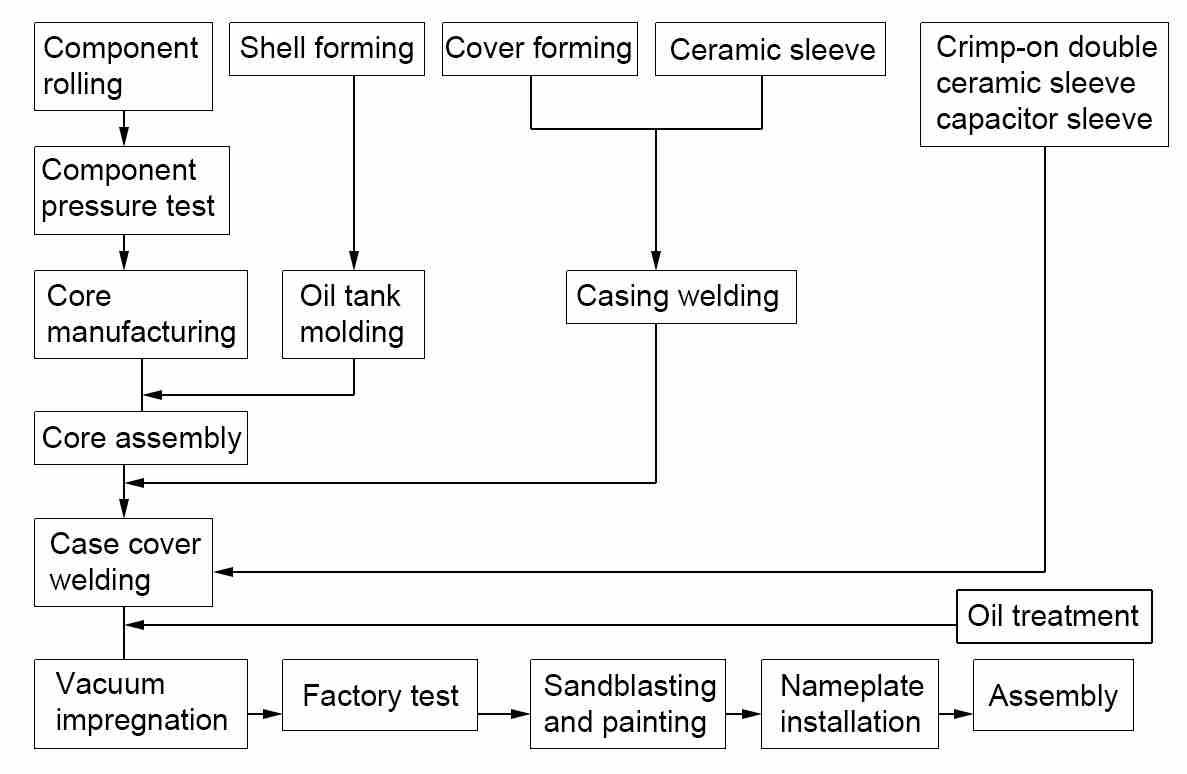
Figure 1 General flow chart of capacitor production
2.Manufacturing process of high-voltage shunt capacitors
2.1 Production of shell, bottom and cover
(1) Cutting and stamping of metal parts: The materials are processed and formed by shearing, punching, drawing, bending and other methods. These include shell, bottom, cover, hanging, etc.
(2) Welding of shell oil tank: Argon arc welding is used to achieve longitudinal seam welding of the shell. The shell and bottom are welded and formed into an oil tank.
(3) Production of the box cover: The integrated sleeve is crimped and welded to the cover using an argon arc welding circumferential seam automatic welding machine. The box cover of the capacitor is completed, as shown in Figure 2.
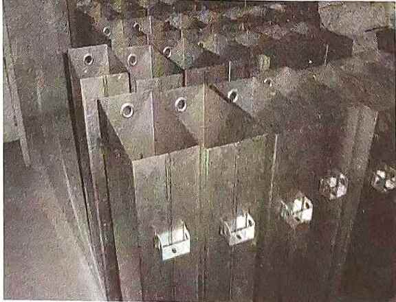
Figure 2 Capacitor shell
2.2 Capacitor core manufacturing
The power capacitors core is composed of components (components consisting of electrodes separated by dielectric and aluminum foil), insulating parts and clamping parts assembled into a whole and properly electrically connected to the main part of the capacitor. The winding of the components (the process of rolling the dielectric material and the electrode material into components according to certain combination requirements) is completed in a clean room. The purification level, indoor temperature, humidity and other processes of the production process have strict requirements. Production can only be carried out when the process conditions are met. The aluminum foil and polypropylene double-sided roughened film (thickness of 10.5-18 μm) with a thickness of generally 6 μm are rolled by a rolling machine in the form of 6 layers of film and 2 layers of aluminum foil, with 3 layers of film between each layer of foil. The capacitor element is shown in Figure 3, and the aluminum foil and polypropylene film are shown in Figure 4.
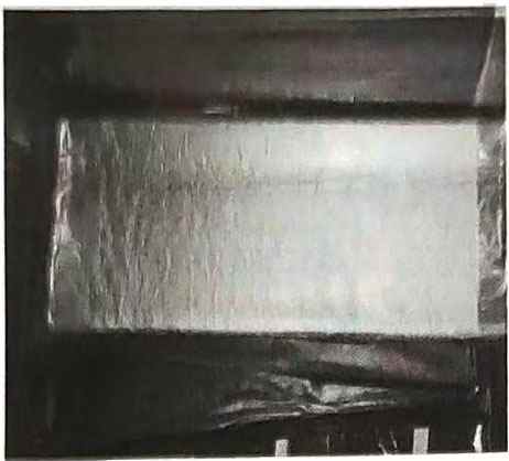
Figure 3 Capacitor element

Figure 4 Aluminum foil and polypropylene film
2.3 Component withstand voltage test
After each component is rolled successfully, the component withstand voltage machine should be used to automatically test the component withstand voltage, and unqualified components should be automatically removed to ensure the quality of the product.
2.4 Core pressing
According to the assembly drawing of the power capacitors core, the splint, components, gaskets, connectors and other parts are placed in sequence. Using the press machine, press the core to a certain height according to the compression coefficient, and then put on a tight hoop or binding strapping tape. The core pressing is completed. Figure 5 shows the core pressing process, and Figure 6 shows the capacitor core group after pressing.
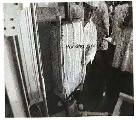
Figure 5 Core pressing process
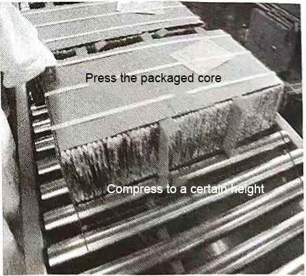
Figure 6 Capacitor core group after pressing
2.5 Core welding
The process of welding the core components according to certain electrical combination requirements.
2.6 Core outsourcing
This process is achieved by the core outsourcing machine.
2.7 Packing
Put the wrapped core (core group) into the oil tank and weld the box cover. The body is placed in the oil tank, and after the body lead is connected to the cover lead, the box cover is welded using a profiling argon arc welding machine. The capacitor to be impregnated after welding is shown in Figure 7.
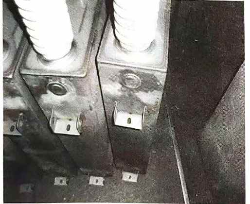
Figure 7 The capacitor to be impregnated after welding
3.Vacuum drying and impregnation treatment of power capacitors
3.1 Purification of insulating oil
This process is mainly used to remove impurities, moisture and gas in the impregnant to make it purer, and its electrical and chemical properties must meet the performance requirements of the capacitor. There are two commonly used insulating oils in my country: S oil PXE phenylxylene ethane and C101-benzyltoluene M/DBT.
3.2 Vacuum impregnation treatment of high voltage parallel capacitors
The vacuum drying and impregnation process is divided into several stages: ① heating, ② low vacuum, ③ high vacuum, ④ oil filling, ⑤ impregnation, etc. After the above process is completed, the product is sealed, and the power capacitors after oil filling and impregnation is shown in Figure 8.
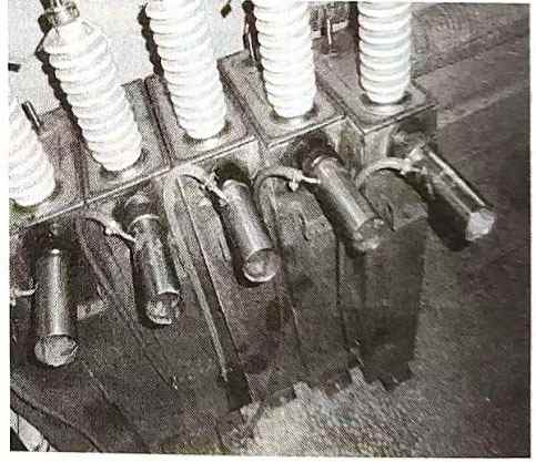
Figure 8 Capacitor after oil impregnation
4.Factory test and follow-up work of high-voltage capacitor products
4.1 Basic requirements of the test
The test of high-voltage capacitors is an examination of the final results of the entire capacitor production. In order to ensure the accuracy and reliability of the test, all tests should be carried out under certain conditions. During the test, attention should be paid to the test environment conditions and records should be kept. There are two types of test environment conditions. One is the artificial environment. In this case, specific provisions are generally made in the product standards; the other is the natural environment conditions. In this case, the test conditions should generally follow the following three rules:
(1) The ambient temperature should be within the range of the standard and the agreement;
(2) There should be no significant difference between the test sample temperature and the ambient temperature;
(3) When the test sample is placed in a constant ambient air temperature for a suitable period of time without power, it is considered to be the same as the ambient air temperature.
4.2 Factory test of capacitors
The purpose of the capacitor factory test is to detect defects in manufacturing and to measure whether the various indicators of the capacitor meet the requirements of the standards and technical agreements. Test order: Capacitance measurement and loss tangent value measurement tests should be carried out after the power frequency withstand voltage test. The order of other tests is not specified. The factory test items are shown in Table 1.
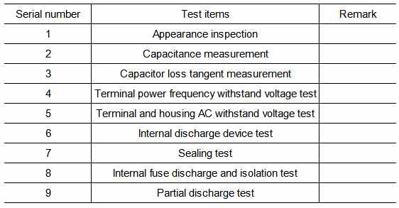
Table 1 Factory test items for capacitors
4.3 Standards to be followed in power capacitors testing
Power capacitors testing should comply with the following standards: GB/T 11024.1-2010 “Parallel capacitors for AC power systems with nominal voltages above 1000V Part 1: General”, GB/T11024.2-2001 “Parallel capacitors for AC power systems with nominal voltages above 1kV Part 2: Durability test”, GB/T 11024.4-2001 “Parallel capacitors for AC power systems with nominal voltages above 1kV Part 4: Internal fuse”, GB/T 20994-2007 “Parallel capacitors and AC filter capacitors for high-voltage DC transmission systems”, DL/T 840-2003 “Technical conditions for the use of high-voltage parallel capacitors”.
4.4 Introduction to factory test methods
(1) Capacitor capacitance measurement. Capacitance measurement is a must-test item for capacitors. Capacitance value is the basic characteristic quantity of capacitors and is used to calculate reactive output capacity.
Methods for measuring capacitance: ① Voltage and current meter method; ② Dual voltage meter method; ③ Bridge method; ④ Capacitance meter direct measurement method.
Under standard ambient temperature, the first three methods are generally used to measure capacitance values at the factory, and the fourth method is generally used on site.
(2) Measurement of capacitor loss tangent value. The purpose of loss tangent value measurement: to check whether there are local defects such as insulation degradation inside the capacitor. In addition to dielectric loss, capacitor loss also includes dielectric loss of pole-to-shell insulation, loss of internal conductive plates, connecting wires and internal fuses, and also includes local discharge loss.
Methods for measuring capacitor loss: ① Current balance method; ② Wattmeter method; ③ AC bridge method (positive wiring and reverse wiring measurement method).
Factors affecting capacitor loss:
1) Dirt on the surface of capacitor porcelain sleeve;
2) Electric field interference and magnetic field interference;
3) The location and length of bridge lead wire;
4) Temperature and humidity of the test environment;
5) The influence of high-voltage standard capacitors;
6) The influence of stray capacitance on the loss of the test product.
(3) Power capacitors AC withstand voltage test. The AC withstand voltage test of capacitors is divided into: terminal-to-terminal withstand voltage test and terminal-to-shell withstand voltage test. Purpose of AC withstand voltage test: AC withstand voltage test is the most stringent, effective and direct test method for identifying the insulation strength of capacitor products. It is also an important means to ensure the insulation level of capacitors and avoid internal failures of capacitors.
Attention should be paid to the voltage rise speed during AC withstand voltage test. The withstand voltage test of capacitors should start from zero potential and increase the voltage evenly to ensure accurate readings on the instrument. When the voltage reaches 75%, it should be increased to 100% at a rate of 2% per second. After maintaining the voltage for a specified time, the voltage should be gradually reduced to zero before the power supply is cut off. It is not allowed to increase the voltage suddenly or cut off the power supply suddenly at a higher voltage to avoid causing destructive temporary overvoltage on the test product.
(4) Inspection of internal discharge devices of capacitors. Most power capacitors have discharge devices inside. Their function is to release the charge to below the specified level within a specified time after the product is disconnected from the power supply, so that the voltage at the capacitor terminal drops to a safe voltage. It is generally stipulated that it drops from 2UN to below 75V within 10 minutes. The test methods include DC charging method and resistance measurement method.
(5) Discharge test of fuses in capacitors. Test purpose: to assess the firmness of the connection between the internal fuse and the component. The test is part of the factory test.
Test method: Apply DC 1.7Us to the capacitor terminals and discharge through the shortest possible circuit. Measure the capacity of the capacitor before and after the test.
Judgment basis: The difference in capacitance change before and after the test is less than the change caused by a fuse blowing. The specific calculation of the capacitance change caused by a fuse blowing will be introduced in the following chapters of this book.
(6) Isolation test of internal fuse of capacitor. The purpose of the test is to test whether the internal fuse can reliably isolate the damaged components in the capacitor.
Test method: The test is carried out at 0.9UN and 2.2UN voltages respectively, using the mechanical puncture method. After the test, a DC current of 3.5UNe is applied between the blown fuses for 10s.
Judgment basis: Before and after the test, the capacitance is measured to prove that the fuse has blown, and the withstand voltage of the fracture and other parts is tested.
(7) Partial discharge test of capacitor. Test purpose: To test the insulation performance of the internal dielectric of the capacitor, which is an effective supplement to the withstand voltage test. It is a non-destructive test and an important means to detect the insulation weaknesses of the capacitor and correct improper design, manufacturing process and material use.
Compared with the AC withstand voltage test, the partial discharge test of power capacitors is a non-destructive test. By measuring the partial discharge of high-voltage capacitor products, the insulation quality of the product can be determined without damaging the insulation performance. The partial discharge test has high sensitivity. Through the test, the weak links in the insulation can be found, and errors in the design and manufacturing process and improper use of materials can be prevented. It is an important method to identify the insulation reliability of the product.
The partial discharge test can make up for the shortcomings of the withstand voltage test. For all factory products, partial discharge tracking tests are carried out, and the test results of partial discharge are recorded and analyzed. The insulation weaknesses in the product can be found out in a timely and accurate manner, and measures can be taken to deal with them appropriately, so that the factory products can operate safely.
Test methods: non-electrical measurement method and electrical measurement method. Non-electrical measurement methods include noise detection method, light wave detection method, heat detection method and air pressure detection method. Electrical measurement methods include radio interference measurement method, high-frequency pulse current measurement method, and pulse polarity identification measurement method. The methods adopted by various manufacturers for partial discharge tests may be different, but the purpose is the same.
4.5 Subsequent work
After the above tests verify that the capacitor is qualified, the subsequent work is mainly sandblasting and painting. Spray protective paint on the metal shell of the capacitor to improve the corrosion resistance and appearance quality of the capacitor. After the paint is qualified, install the nameplate, assemble, and put into storage until it leaves the factory.