1 Concept And types of Dislocation
Capacitors – Dislocations in Aluminum. The structure of aluminum crystal given in Figure 1.1 and Figure 1.2 is an ideal complete structure. Studies have found that there will be certain incompleteness and defects in the three-dimensional arrangement of atoms in crystals, that is, the rules of atomic arrangement are destroyed in some parts. The scale of one kind of defect is smaller in two directions and larger in another direction, showing a linear range, and the atomic arrangement in this range is seriously irregular. The configuration of seriously irregular atomic arrangement in the linear range of the crystal is called a dislocation.
Aluminum crystals have very low resistance to plastic deformation and very good plastic deformation ability. The yield strength of high-purity aluminum is only 15~20MPa, while its elongation can be as high as 70%, that is, it has the ability to undergo large-scale permanent deformation without destroying its basic structure. The plastic deformation of metals is achieved by the sliding of metal atoms along specific crystal planes. Figure 1.18 (a) schematically shows a complete crystal structure. If metal atoms slide along a crystal plane at the same time as a whole, the calculated theoretical strength is very high. If, as shown in Figure 1.18(b), the atoms in the crystal make local relative displacements, so that the regular arrangement of atoms becomes dislocation due to misalignment along one direction, then under the action of shear stress, the dislocation with the local irregular arrangement of atoms gradually moves on the sliding surface to perform sliding deformation [as shown in Figure 1.18(a)~(d)]. This movement of dislocation is called slip, and the surface provided for the dislocation to slip is called the slip surface. In this way, the atomic bonds between the two adjacent atomic planes above and below the slip surface are not destroyed as a whole at the same time, but are destroyed in sequence one by one, so the maximum shear stress required is greatly reduced. The emergence of dislocation theory has well revealed the reason why the real strength of crystals is much lower than the theoretical strength. Studies have shown that all problems involving the mechanical behavior and mechanical properties of materials, such as deformation and strength, are closely related to dislocations!

Capacitors – Dislocations in Aluminum Figure 1.18 Schematic diagram of the slip process of a dislocation
There is an elastic distortion zone around the dislocation, and it has a large scale only in one dimension, while the other two-dimensional scales perpendicular to it are very small, usually involving only a few atoms. The direction of the large scale of the dislocation is regarded as the direction of the dislocation line, represented by vector t, called the dislocation line direction vector. The dislocation line will not have an endpoint inside the crystal. It either forms a closed dislocation line of some form, or ends on the surface or internal interface of the crystal. Dislocations are mainly divided into two basic forms, one is the edge dislocation (abbreviated as edge dislocation) and the other is the screw dislocation (abbreviated as screw dislocation). Figures 1.19 (a) and (b) show schematic diagrams of these two dislocations in the crystal. Among them, the number of atomic planes perpendicular to the slip plane shown in Figure 1.18 near the edge dislocation is different on the upper and lower sides of the slip plane. One side has an extra atomic plane, which is called the extra half-atomic plane; there is no such plane in the screw dislocation.
If we artificially define the positive direction of the dislocation line direction vector t, and make a right-hand closed loop around the dislocation line t direction at a distance far enough from the dislocation line and reaching an almost complete crystal with the full atomic spacing as the step length: then after making the same loop in the complete crystal with the full atomic spacing as the step length, it must be open. The vector from the end point (loop arrow) of this open loop to the starting point (small circle) is called the Burgers vector (referred to as the Burgers vector), represented by vector b. The Burgers vector reflects the distortion around the dislocation line in the crystal structure. Figure 1.19 (c) compares Figure 1.19 (a) and Figure 1.19 (b) respectively, and uses the Burgers loop to determine the Burgers vectors of edge dislocation and screw dislocation. The characteristics of different types of dislocations can be expressed by the Burgers vector b and the dislocation line direction vector t of the dislocation. The Burgers vector b of the edge dislocation and the dislocation line direction vector t are perpendicular to each other, and the Burgers vector b of the screw dislocation and the dislocation line direction vector t are parallel to each other. Any other dislocation can be decomposed into edge dislocation components and screw dislocation components. A dislocation formed by the superposition of an edge dislocation component and a screw dislocation component is called a mixed dislocation. The Burgers vector b and the dislocation line direction vector t of a mixed dislocation are neither perpendicular nor parallel [Figure 1.19(d)].
 Capacitors – Dislocations in Aluminum Figure 1.19 Dislocation in crystal (gray area is slip plane):
(a) edge dislocation (Bergers loop 1); (b) screw dislocation (Bergers loop 2);
(c) determination of Burgers vector; (d) mixed dislocation (bend of dislocation line)
A dislocation line can extend and distribute in a zigzag manner in a crystal, but as long as it does not intersect with other dislocation lines, it can only have a unique Burgers vector b [Figure 2.19 (d)]. Therefore, as the bending of the dislocation line changes, the edge and screw characteristics of the dislocation will also change. When several dislocation lines merge into one dislocation line or one dislocation line decomposes into several dislocation lines in a crystal, the Burgers vector of the combined dislocation line is the sum of the Burgers vectors of these dislocation lines. Because the Burgers vector characterizes the direction of the relative displacement between the dislocated atoms caused by the dislocation and the magnitude of the total displacement, the merger of several dislocation lines is actually the merger of the direction of the relative displacement between the dislocated atoms caused by each dislocation and the magnitude of the total displacement, and the result must become the direction of the relative displacement between the dislocated atoms in the new dislocation and the magnitude of the total displacement.
Figure 1.20(a) shows the dislocation observed by transmission electron microscopy on annealed high-purity aluminum foil. The end point of the dislocation line actually extends to the surface of the observed film sample, not inside the sample [Figure 1.20(b)]. In Figure 1.20(a), it can also be observed that some dislocation lines intersect and merge with each other. The average spacing of the dislocation lines is about micrometers.
Capacitors – Dislocations in Aluminum, the above is the concept and type of dislocation.
2 Dislocation Stress Field And Dislocation Energy
As shown in Figure 1.21 (a), imagine introducing a straight screw dislocation line in an elastic hollow cylinder. First, cut the cylinder along the ABCD plane, so that the two cut surfaces are relatively displaced by b along the z direction, and then glue the two cut surfaces together. In this way, shear strain ε is generated in the cylinder. If the surface of the cylinder with radius r is unfolded, as shown in Figure 1.21(b), the shear strain ε is
According to Hooke’s law, the corresponding shear stress is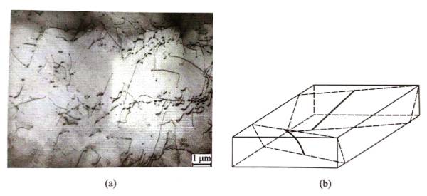
Capacitors – Dislocations in Aluminum Figure 1.20 Observation of annealed state using transmission electron microscopy
(a) Dislocation line of high-purity aluminum foil and (b) phenomenon of dislocation line extending to the surface of the sample

Where G is the shear modulus. Except for the shear stress T, no other stress can be derived near the screw dislocation. Therefore, there is only a shear stress component in the stress field of the screw dislocation, but no normal stress component, and the shear stress T is only related to the distance r from the center of the dislocation line, and has nothing to do with the z value in the 0 and z-axis directions shown in Figure 1.21(a). It can be seen that the stress field around the screw dislocation is symmetrical about the z-axis, that is, the stress is equal at all points on the cylindrical surface with the dislocation line as the axis, and the larger the radius of the cylindrical surface, the smaller the stress. Equation (1.13) is derived under the simplified environment in Figure 1.21(a) and cannot be applied to the dislocation center area; because when r approaches zero, the shear stress will approach infinity, which is obviously not in line with the actual situation.
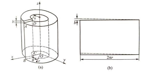
Figure 1.21 Illustration of the derivation process of the stress field formula for a straight screw dislocation;
(a) Introducing a straight screw dislocation into a crystal; (b) The shear strain εθz at any point r in the screw dislocation
The stress state in a three-dimensional solid can be expressed as a stress field. The stress field described by {δ} is a tensor that contains the surface, direction, and magnitude of the stress. The stress tensor can be expressed by a 3×3 matrix, including 3 normal stress components and 6 shear stress components. When δij is used to represent the stress component, the subscript i represents the normal direction of the surface on which the force acts, and j represents the direction of the force. i=j is the normal stress, and i≠j is the shear stress. In static equilibrium, aij=δij. Therefore, there are only 6 independent stress components. In the cylindrical coordinate system given in Figure 1.21, the stress field of a screw dislocation with a Burgers vector b in an aluminum crystal with a shear modulus of G=25.9 GPa |σ) can be expressed as
After converting the stress field, the stress field expression in the rectangular coordinate system shown in Figure 1.21 (a) can be obtained:

From formula (1.15), it can be seen that the stress field of the screw dislocation is a pure shear stress field without normal stress. The stress field generated by the dislocation in the surrounding medium will cause a certain elastic strain energy Eel o. It is still difficult to estimate the divergent stress at the core of the dislocation. The elastic strain energy calculated using the dislocation stress field is divergent. After appropriate simplification, the elastic strain energy per unit length of the straight screw dislocation Eel ocan be obtained.

Where: R is the influence range of the dislocation stress field, which can actually be taken as half of the average spacing of dislocations in the crystal; ⋏≈0.5 is the reference coefficient. For most metals, if the energy of the dislocation core is also estimated in the equation, ⋏ can be taken as 1/4.
In the spatial rectangular coordinate system shown in Figure 1.22, assume that the dislocation line of the straight edge dislocation passes through the origin and is parallel to the z-axis, the direction of the Burgers vector is parallel to the x-axis, and the third direction perpendicular to the dislocation line direction vector and the Burgers vector is the y-axis. Based on the equilibrium equation expressed by the displacement field caused by the dislocation, the elastic stress field σ of the straight edge dislocation can be obtained.
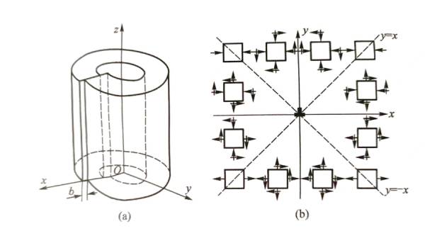
Capacitors – Dislocations in Aluminum Figure 1.22 Stress field of straight edge dislocation:
(a) Introducing a straight edge dislocation in a crystal; (b) Stress distribution around the edge dislocation

Where, v=0.36, is the Poisson’s ratio of aluminum. According to the stress distribution characteristics near the straight edge dislocation shown in formula (1.17), the influence of the stress field on the surrounding medium can be qualitatively analyzed. Figure 1.22 (b) is a simple graph describing the properties of the stress field around the edge dislocation. When y=0, the normal stress is zero, there is only shear stress, and the shear stress is the maximum value; when x=±y, σxy=σyy=0; when x=0xy, σ=0. When the extra half-atomic plane of the edge dislocation is in the y<0 region, its stress field has the opposite sign to that given by formula (1.17).
With the help of the stress field of the straight edge dislocation, and after appropriate simplification, the elastic strain energy Ee el of the straight edge dislocation per unit length can also be obtained Eeel:
Comparing the expressions (1.18) and (1.16) of the elastic strain energy of the edge dislocation and the screw dislocation, it can be seen that Eeel is 1/(1-v) higher than Eeel, about 1.5 times, that is, the edge dislocation has higher energy.
The mixed straight dislocation can be regarded as a superposition of a dislocation consisting of an edge component and a screw component. From the stress fields of edge dislocation and screw dislocation in equations (1.17) and (1.15), they will not have non-zero components at the same time; therefore, the two stress fields are orthogonal and do not affect each other. Assuming that the angle between the Burgers vector b of the mixed straight dislocation and the dislocation line direction vector t parallel to the z-axis is φ, the edge dislocation component of the Burgers vector of the mixed dislocation is be.=bsinφ, and the screw dislocation component is bs.=bcos φ. Therefore, the stress field {σ}„ of the mixed dislocation can be a simple superposition of its edge dislocation stress field component and screw dislocation stress field component, that is,

The mixed dislocation energy is also the superposition of the energy of the edge and screw dislocation components, so the energy of the straight mixed dislocation per unit length is Emel.

Among them:
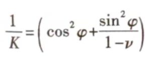
In fact, equations (1.19) and (1.20) also include the cases of edge dislocation and screw dislocation: for screw dislocation, φ=0°, K=1; for edge dislocation, φ=90°, K=1 -v.
From the above formula, it can be seen that, relatively speaking, the energy of a dislocation line per unit length has little to do with the type of dislocation and the logarithmic value of R. The R value of actual materials is in the order of microns or submicrons. It can be considered to increase the R value appropriately so that the dislocation energy can also include a small amount of energy in the core area of the dislocation in Figures 1.21 (a) and 1.22 (a); R can be taken as several times of b. After substituting it into formula (1.20), the energy of all dislocations Eel. can be approximately expressed as:

Where kd is 0.5~1. This can estimate the energy of dislocations in the crystal.
Capacitors – Dislocations in Aluminum The above is an analysis of dislocation stress field and dislocation energy.
3 Capacitors – Dislocations in Aluminum Slip of dislocations in Aluminum
From equation (1.21), it can be seen that the energy of a dislocation is proportional to the square of the length of its Burgers vector, so the Burgers vector should be as short as possible to keep the dislocation at the lowest energy. On the other hand, after the dislocation slips, that is, after the crystal moves relatively along the slip plane by a Burgers vector, the structure of the crystal cannot change, otherwise it will cause a substantial increase in energy. The shortest translation vector that keeps the crystal structure unchanged in aluminum crystals is 1/2 of the <110> crystal direction in the unit cell shown in Figure 1.3, that is, the nearest neighbor distance of aluminum atoms; therefore, the length b of the Burgers vector of a pure aluminum dislocation is 0.2863 nm (Figure 1.1), or expressed as b=<110>a/2 using the unit cell constant. Referring to Table 1.2, it can be seen that aluminum crystals have a total of 6 non-parallel Burgers vectors along the <110> direction. Studies have shown that the planes on which dislocations are prone to slip are mostly the most densely packed planes of their atoms. The most densely packed plane of aluminum crystals is the {111} plane, so its slip plane is the {111) plane. Referring to Table 2.2, it can be seen that aluminum crystals have a total of 4 non-parallel |111} planes. Each {111} plane can have 3 non-parallel <110> Burgers vectors, that is, each {111| plane can have 3 different dislocation slips. The combination of the slip plane and the direction of the Burgers vector on which the crystal undergoes relative translation is called a slip system. The slip system is represented by the slip plane and the Burgers vector index, such as (111)[101]. It can be seen that aluminum crystals have a total of 3×4=12 different potential slip systems, corresponding to 12 dislocations with different slip planes and Burgers vectors. If the slip along the positive and negative directions of the Burgers vector is regarded as two slip systems, then aluminum crystals have a total of 24 slip systems.
Figure 1.23(a) shows the unit cell of the aluminum crystal shown in Figure 1.2. Now connect the two unit cells as shown in Figure 1.23(b), paint the atoms on the different (111) planes parallel to each other in the two unit cells white, black and gray respectively, and observe the differences in the distribution of atomic positions on different (111) planes. Assume that the white atoms at the origin of the unit cell are atoms on a (111) plane passing through the origin, then the (111) plane closest to the origin is occupied by black atoms, the (111) plane next to the origin is occupied by gray atoms, and the (111) plane next to the origin is occupied by white atoms, as shown by the atom marked by the character A in Figure 1.23(b). If you start from the origin atom and observe toward atom A along the [111] direction perpendicular to the (111) plane, you will find that atom A completely overlaps with the origin atom, but does not overlap with black atoms or gray atoms, as shown in Figure 1.23(c).
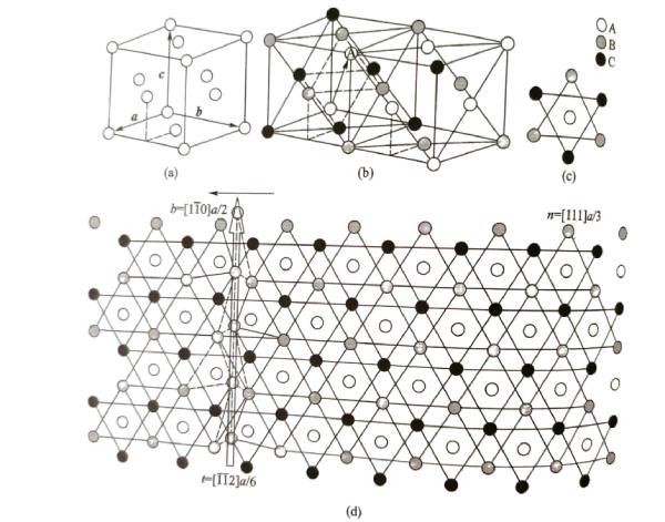 Capacitors – Dislocations in Aluminum Figure 1.23 Schematic diagram of edge dislocation slip on the (111) plane of aluminum crystal
Assuming that the black atomic plane and the gray atomic plane that constitute the (111) plane are slip planes, when an edge dislocation with a Burgers vector of [110]a/2 appears or sweeps across the slip plane by means of slip, the gray atomic plane and all the atomic planes above it will have an extra row of atoms relative to the black atomic plane, and these extra atoms are combined to form the extra half atomic plane shown in Figure 1.18. Figure 1.23 (d) schematically shows an edge dislocation with a dislocation line direction of [112]a/6 and a Burgers vector of [110]a/2 on the (111) plane of aluminum crystal observed along the [111] direction.
Capacitors – Dislocations in Aluminum – The above is an explanation of the slip of dislocations in aluminum
4 Capacitors – Dislocations in Aluminum Force on Dislocations
When a certain stress field acts on the crystal, it may promote the movement of dislocations in the aluminum crystal. During rolling, the external stress will be converted into shear stress on the slip plane, and promote a large number of dislocations to slip, causing macroscopic plastic deformation.
If the stress field acting on the crystal is converted into shear stress on the slip plane in the direction perpendicular to the dislocation line (Figure 1.24), and the dislocation line with a length of L moves a distance dS on the slip plane; then when T represents the stress, its action area (gray area in Figure 1.24) is Lds, and the total force is TLdS. After the dislocation slips, the relative distance of the atomic planes on both sides of the area swept by the dislocation line is the length b of the Burgers vector; therefore, the work done by the external force on the dislocation slip is TbLdS. Assume that the force perpendicular to the unit dislocation line is f, then the force on the L-length dislocation line is fL, 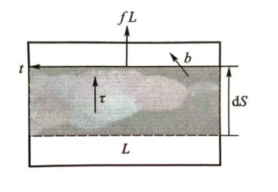
Figure 1.24 Schematic diagram of dislocation force analysis
and the energy consumed by the dislocation line slip ds is fLdS. T is the shear stress, and f is the slip force on the dislocation line. According to the principle of conservation of energy, the work done by the external force on the dislocation slip is equal to the energy consumed by the dislocation line slip, so:
![]()
The energy of a dislocation increases with its length, so it tends to shorten. This tendency is manifested as the linear tension of the dislocation; the linear tension Г is approximately equal to the energy of the dislocation per unit length [Formula (1.21)], that is, Г=kd. Gb2From the physical essence, a dislocation will be subject to force under the action of its own stress field. The linear tension of a straight dislocation line is equal to 0, but the linear tension of a curved dislocation line is not 0. The linear tension of a curved dislocation line can be simply analyzed and calculated by an approximate method. Suppose a curved dislocation line is subjected to a force pointing to the center of curvature. This force tends to straighten the dislocation line. The dislocation can only remain in a curved state when there is an opposite external force. Suppose there is a curved dislocation arc with a curvature radius of R on the slip plane, its length is δs, and the central angle corresponding to the center of curvature of the arc is δ0 (as shown in Figure 1.25). The force generated by the line tension on δs pointing to the center of curvature is 2Гsin(δ0/2)≈T80=ГδS/R.
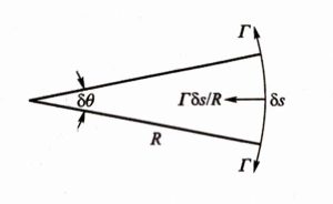
Figure 1.25 Curved dislocation line segment under line tension
If this curved state is to be maintained, a force f of the same magnitude and opposite to the above force must be added to δs. The slip force per unit length of the dislocation line under the external stress field is Tb [Formula (1.22)]. The curved dislocation has the following relationship when in equilibrium:
 That is, the shear stress on the curved dislocation is

Dislocations form a stress field in the crystal around them, so the stress fields of two adjacent dislocations in the crystal may interact with each other, resulting in mutual forces between dislocations. The magnitude of the mutual forces between the two dislocations is equal and the direction is opposite. A simple way to discuss the mutual forces between two dislocations is to regard the stress field of one dislocation as the stress represented by equation (1.22) and act on the other dislocation, and vice versa.
As shown in Figure 1.26, there are two parallel straight screw dislocations A and B with a distance of r in the same direction, and their Burgers vectors are bA and bBrespectively. Assume that both dislocation lines are parallel to the z-axis of the cylindrical coordinates, and dislocation A passes through the origin of the coordinates, and the slip plane of dislocation B is set to the coplanar plane of the two dislocations. According to equations (1.22) and (1.13), the force per unit length of dislocation A on dislocation B is

As shown in Figure 1.26, the force between two dislocations of the same sign is repulsive. At the same time, the unit length of dislocation A is also subjected to an equal and opposite force from dislocation B.
As shown in Figure 1.27, two parallel straight edge dislocations A and B with a distance of r in the same direction have Burgers vectors bA and bB respectively. Put dislocation A on the z-axis of the coordinate system, its slip plane is the xOz plane, and dislocation B is at (x, y). First calculate the force per unit length of dislocation A on dislocation B on the slip plane, fgA-B. The normal direction of the slip plane of dislocation B is the y direction, and the direction of the Burgers vector is the x direction, so:

The direction of the force is in the x direction. Let’s look at the force fgA-B on the normal of the extra half-atomic plane of unit length dislocation B. The direction of the Burgers vector of dislocation B is in the x direction, so:

The direction of the force is the y direction.
If the two dislocations are of opposite signs, the direction of the force is opposite to the above. It is not difficult to see from equations (1.26) and (1.27) that the magnitude and direction (positive sign indicates the direction pointing to the positive direction of the coordinate, negative sign indicates the direction pointing to the negative direction of the coordinate) of the interaction force between two parallel straight edge dislocations of the same sign in a parallel slip plane vary with the relative position (x, y or r, θ) between the two dislocations. For a pair of edge dislocations [Figure 1.28(a)] or screw dislocations [Figure 1.28(c)] with opposite Burgers vectors on the same slip plane, their stress field will drive the two dislocations closer to each other and eventually cancel each other out, restoring the original dislocation area to a complete crystal [Figure 1.28(b), (d)].
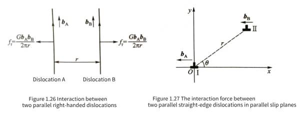

Figure 1.28 Schematic diagram of a pair of opposite dislocations on the same slip plane canceling each other out (the dotted line is the screw dislocation line)
Because the stress fields of parallel edge dislocations and screw dislocations are orthogonal and there are no overlapping stress components [see equations (1.17) and (1.15)], there is no interaction between parallel screw dislocations and edge dislocations.
In a bulk aluminum crystal, the change in energy of a straight dislocation due to the change in dislocation position is very small and can be ignored, so the straight dislocation will not be subjected to stress due to its own stress field. However, if the dislocation is close to the free surface, part of its strain energy will be relaxed, and the closer to the surface, the more energy will be relaxed. In order to reduce energy, dislocations tend to escape from the surface, that is, the free surface has an attractive force on the dislocation. Assuming a straight screw dislocation parallel to the surface and at a distance of L from the surface, referring to formula (1.16), its elastic strain energy per unit length is

Compared with formula (1.16), L is used to replace R here, because the range of the stress and strain field of the dislocation needs to be estimated by the distance L from the dislocation to the surface. According to the definition of force and referring to formula (1.15), the attractive force of the free surface on the dislocation per unit length is fim

This force is equivalent to the force exerted on the real dislocation by a virtual dislocation of opposite sign (Figure 1.29) on the outside of the free surface in a mirror-symmetrical position with the dislocation. Therefore, the force exerted by the surface on the dislocation can be expressed by the method of imaginary dislocation. Because this imaginary dislocation is in the image position of the real dislocation relative to the free surface, it is called an image dislocation. The force exerted on the dislocation by the free surface is therefore also called an image force.
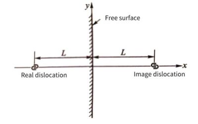
Capacitors – Dislocations in Aluminum Figure 1.29 Screw dislocation close to the free surface and its corresponding image dislocation
The image force of the edge dislocation can also be calculated by referring to formula (1.17) in the same way, and the result is

When the image shear stress borne by the dislocation exceeds the critical shear stress required for the aluminum dislocation to slip, the dislocation will begin to slip. Therefore, the dislocation near the surface may escape from the surface under the action of the image force. Assume that the critical shear stress that causes the dislocation to start slip is 7. Substituting it into formula (1.30), we have:

Where, do is the maximum distance, or critical distance, that a straight edge dislocation near the free surface and parallel to the surface can slide toward the surface along a slip plane perpendicular to the surface under the action of the imaging force. Equation (1.31) shows that a straight dislocation approaching the free surface of a metal in the manner shown in Figure 1.29 will escape from the surface when its distance from the surface is less than d0.
For 99.996% AI high purity aluminum, G=25.9 GPa, b=0.286 3 nm, v=0.36, T. ≈1 MPa The calculated d88 value is about 1um. It can be seen that if a free surface appears in aluminum foil under a reducing atmosphere or environment, the dislocation state within 1um below the surface may change under the action of the imaging force, and even escape from the surface, thereby reducing the dislocation density. Of course, real dislocations are not necessarily parallel to the surface, and there will be certain entanglements and chains between dislocations [Figure 1.20 (a)], which will restrict the escape of dislocations. When an oxide film is formed on the surface of aluminum foil, its dislocation configuration becomes more complicated.
Capacitors – Dislocations in Aluminum-The above is an explanation of the force on dislocations.
5 Capacitors – Dislocations in Aluminum Proliferation of Dislocations
Dislocations can only slip on the plane determined by their Burgers vector and the dislocation line direction vector. The Burgers vector of the edge dislocation and the dislocation line direction vector are perpendicular to each other, so its slip plane is uniquely determined. However, the Burgers vector of the screw dislocation and the dislocation line direction vector are parallel to each other, so the screw dislocation can have multiple slip planes. Under the action of shear stress, when the slip of the screw dislocation line on the initial slip plane is blocked by an obstacle and cannot continue to slip, it is possible to change to another slip plane that intersects with the initial slip plane and is parallel to the dislocation line to continue slipping. This slip motion is called cross slip. Edge dislocations cannot cross slip.
If a screw dislocation whose slip is blocked passes over the obstacle through cross slip, and then uses the cross slip mechanism to return to the slip plane parallel to the original slip plane to continue sliding, this slip motion is called double cross slip. Figure 1.30 is a schematic diagram of the double cross slip motion of the screw dislocation line. The screw dislocation line initially moves to the left in the slip plane ABCD. After encountering the obstacle represented by the black stain, it cross-slips to the CDEF plane through the intersection line CD with the CDEF plane and continues to move. After properly slipping to avoid the obstacle, it can cross-slip again through the intersection line EF to the EFGH plane parallel to the original ABCD to continue normal slip. The starting position of the dislocation line of the screw dislocation is AB, and after double cross slip, it finally reaches the CH position (Figure 1.30)
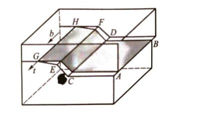
Capacitors – Dislocations in Aluminum Figure 1.30 Schematic diagram of double cross-slip of a screw dislocation line (black spots are obstacles to screw dislocation slip)
Although dislocation is a non-equilibrium defect, a certain number of dislocations are always retained in the crystal. After sufficient equilibrium treatment, the dislocation density in aluminum crystals, that is, the length of the dislocation line per unit volume, will also be 10~10″m/m*]. The plastic deformation of aluminum is mainly completed by dislocation slip. Each dislocation can only provide an atomic spacing range, that is, a slip amount of 0.2863nm after escaping the crystal by slip; therefore, a large amount of dislocation slip is required to achieve a large permanent deformation. However, people have found that after a large deformation, the dislocation density in aluminum crystals not only does not decrease, but is greatly increased. For example, after a large low-temperature deformation, the dislocation density in the metal can be as high as 1010~1014m/m3. This shows that dislocations will multiply in large numbers during the deformation of metal crystals. Dislocations can multiply in many ways, and the part of the crystal that causes dislocations to multiply is called a dislocation source. A typical dislocation multiplication source is the Frank-Read dislocation source.
Figure 1.31 shows the process of dislocation proliferation caused by a Frank-Reed dislocation source (abbreviated as F-R dislocation source). In the figure, A and B are two nodes on a dislocation line that are pinned and cannot move for some reason. A segment of dislocation between AB is on a slip plane parallel to the paper. Under the action of external force, the dislocation line is subjected to force, and bends and expands along the force direction. Figures 1.31 (a), (b), (c), (d) and (e) show the process of dislocation line bending and expansion. Note that the dislocations at C and C’ in Figure 1.31 (d) are dislocations of opposite signs. They attract each other, contact and merge, and the sum of the Burgers vectors is 0, that is, the contact parts of the two dislocations merge and cancel each other (Figure 1.28), so that the original dislocation is divided into two parts: one part is a complete dislocation loop, and the other part returns to the original AB position. Under the action of external force, the dislocation loop continues to expand and slip around and cause the metal to continuously grow permanent deformation. The AB dislocation segment will again use slip to create a new dislocation loop. The continuous repetition of this process can continuously release dislocations, so that the dislocation density in the crystal continues to increase. If a dislocation on a screw dislocation line enters another slip plane with the help of the double cross slip mechanism shown in Figure 1.30, and the other parts of the screw dislocation line do not cross slip due to the resistance of slip, then the two ends of the dislocation that undergoes double cross slip may be pinned and become a F-R dislocation source [Figure 1.31 (f)]. When the dislocation sliding is blocked by other obstacles, F-R dislocation sources will be generated similarly, causing dislocation proliferation.
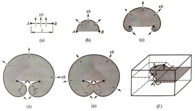
Capacitors – Dislocations in Aluminum Figure 1.31 Schematic diagram of F-R dislocation source multiplication dislocation
The dislocation density can also be converted from the length of the dislocation line per unit volume to the number of intersection points with the dislocation line per unit section or the number of dislocation outcrops per unit section, in units of cm-2. It can be proved that the length of the dislocation line per unit volume is twice the number of dislocation outcrops per unit section. The dislocation density of annealed aluminum is 1010″m/m88′, and the corresponding number of dislocation outcrops per unit cross section is 0.5x(10m10~1014)/m2. The two are of the same order of magnitude, so there is no difference in principle. Sometimes the two can also be considered equal. From this, it can be estimated that the average spacing of dislocation lines in annealed aluminum reaches the range of 0.1~10um, which is roughly consistent with the observation in Figure 1.20(a). After large-scale cold deformation, the average spacing of dislocation lines in aluminum is reduced to the range of 1~10nm.
Capacitors – Dislocations in Aluminum-The above is an explanation of dislocation proliferation
6 Dislocation State And Normal Stress Field on The Surface of Aluminum Foil
The aluminum foil of electrolytic capacitors needs to be corroded. The corrosion starts from the surface of the aluminum foil. When the dislocation inside the aluminum crystal extends to the surface of the aluminum foil, it will have an important impact on the corrosion behavior. It is well known that the tensile stress on the surface of metal materials will promote the corrosion. When the dislocation extends to the surface of the aluminum foil, it will bring the stress field of equations (1.15), (1.17), and (1.19) to the surface. Therefore, when the density of the outcrops on the surface of the aluminum foil increases, the corrosion of the aluminum foil will be promoted.
As mentioned above, dislocations close to the surface and with dislocation lines parallel to the surface will be affected by the imaging force, and may migrate to a certain extent, or even escape from the surface. When the dislocation line is not parallel to the surface, the dislocation may also adjust its configuration. As shown in Figure 1.32, there is an edge dislocation with a Burgers vector of b and a dislocation line direction vector of t88. When its dislocation line is bent into a dotted line under the action of the image force, the total length of the dislocation line and the total dislocation energy decrease. Therefore, this bending is an energy-favorable spontaneous process, and its deflection angle can be specifically calculated.
The energy of the dislocation line per unit length is proportional to b2. Comparison of equations (1.18) and (1.16) shows that the elastic energy of the edge dislocation is 1.5 times that of the screw dislocation, that is, the edge dislocation has a higher energy. Therefore, a straight edge dislocation perpendicular to the surface with a Burgers vector of b2 and a dislocation line direction vector of t2 may also be slightly bent into a dotted line (Figure 1.32). Once the dislocation line is bent, the dislocation is no longer a pure edge dislocation, but contains a small amount of screw dislocation components and edge dislocation components. Although the sum of the squares of the two decomposed dislocation Burgers vectors is the same as before the bending, the energy of the unit screw dislocation is lower, which can still reduce the total energy. It should be noted that this bending (Figure 1.32) increases the total length of the dislocation line, so the bending can only be done until the energy reduction caused by the increase in the screw dislocation component is balanced by the energy increase caused by the increase in the total length of the dislocation line.
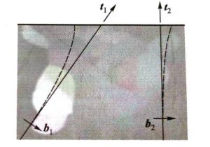
Capacitors – Dislocations in Aluminum Figure 1.32 Stable configuration when the dislocation line extends to the free surface of the aluminum foil
(the thick horizontal line at the top represents the surface of the aluminum foil)
The stress field given by equations (1.15), (1.17) and (1.19) uses the dislocation line direction vector, Burgers vector and slip plane as the reference coordinate system. The Burgers vector and slip plane of the dislocation in aluminum are known crystal directions and crystal planes. When the aluminum foil has certain specific crystal planes as the surface, the stress field given by equations (1.15), (1.17) and (1.19) cannot directly give the stress field on the surface of the aluminum foil. Therefore, appropriate stress field conversion is required to obtain the actual stress on the surface of the aluminum foil.
The most common crystal plane families on the surface of the anode aluminum foil are {100} and {123}. When the aluminum foil has the {100} plane as the surface, 4 of the 12 dislocations will be transformed into pure screw dislocations and escape from the surface under the action of the image force, and the other 8 will have the same stable configuration and stress field. When the aluminum foil has the {123} plane as the surface, there will be 11 configurations and stress fields with different stress levels among the 12 dislocations. Generally speaking, the pure screw dislocation given by formula (1.15) has no positive stress component, and after being converted into {100| or {123| surface stress, its stress level is relatively low; while the positive stress level of the edge dislocation and its conversion into a stable configuration is relatively high, which has a more important impact on the corrosion behavior.
Placing the dislocation outcrop at the origin, Figure 1.33 shows the tensile stress distribution near the stable dislocation line outcrop on the {100} plane, as well as the tensile stress distribution near the two dislocation line outcrops with the highest stress level (denoted as {123}H) and the lowest stress level (denoted as {123}L) among the various stable dislocation line outcrops on the {123} plane. Comparing the levels of stress fields near the dislocation line outcrops on the two planes, the stress level of the dislocation outcrops on the {100} plane is at an intermediate level. The gradients of tensile stress changes at the dislocation line outcrops on the {100} and {123} planes are not the same when leaving the dislocation center in all directions, and the highest tensile stress gradient should be more conducive to promoting corrosion. Figure 1.34 shows the stress in the direction of the maximum tensile stress gradient at the three dislocation outcrops in Figure 1.33. Comparison found that a very high stress will be maintained near some dislocation line outcrops on the {123} plane, so the {123} plane is more susceptible to corrosion and pore formation with the help of dislocation outcrops than the {100} plane. This is consistent with actual observations.
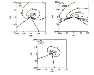
Figure 1.33 Distribution of tensile stress at dislocation line outcrops on the {100} and {123} planes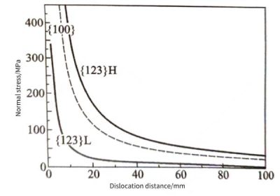
Figure 1.34 Relationship between the maximum positive stress (MPa) at the outcrop of the dislocation line on the {100} plane and the {123} plane and the normal stress in the gradient direction and the distance from the center of the dislocation line (mm)
(The {123} plane gives the highest (H) and lowest (L) stress dislocation values respectively)
It should be pointed out that the dislocation stress field given by equations (1.15), (1.17) and (1.19) is a simplified stress expression, which will be different from the real dislocation stress field. On the other hand, when the dislocation line extends to the surface of the aluminum foil and contacts the free space, the stress value of the dislocation will be reduced due to a certain release. Therefore, Figures 1.33 and 1.34 are only the results of an approximate calculation. However, this calculation can roughly reflect the difference in tensile stress levels near the outcrops of dislocations on different crystal planes, which is conducive to analyzing the reasons for the differences in corrosion pore behavior on different crystal planes. At present, the precise calculation method of dislocation stress on the surface of aluminum foil needs to be further studied.
Capacitors – Dislocations in Aluminum- The above is a description of the dislocation state and normal stress field on the surface of aluminum foil
Capacitors – Dislocations in Aluminum-Summary:
Capacitors – Dislocations in Aluminum- Dislocations are an important type of defect in crystalline materials, which have a significant impact on the mechanical properties and deformation behavior of the material. The following is a detailed description of the concept, type, stress field and energy of dislocations, slip behavior in aluminum, force, proliferation phenomenon, and dislocation state and normal stress field on the surface of aluminum foil.For more information about Xuansn capacitors, please click:https://www.xuanxcapacitors.com

