1 Snap-in electrolytic capacitor—Packaging form
Snap-in electrolytic capacitor—are medium and large electrolytic capacitors, most of which are directly mounted on the circuit board. Since snap-in electrolytic capacitors come in a wide range of sizes, different pin patterns are required for reliable mounting on the circuit board.
Figure 1-1 shows a two-pin electrolytic capacitor package.
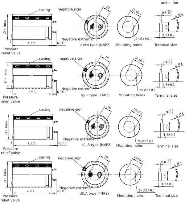
Figure 1-1 Two-pin electrolytic capacitor package
In order to prevent the electrolytic capacitor from falling off the circuit board during the assembly and welding process, the pins are designed to be curved. After being inserted into the corresponding mounting holes of the circuit board, the pins can be “stuck” in the mounting holes.
The dimensions of the pins and the dimensions of the mounting holes for the pins on the circuit board are also shown in Figure 1-1.
Electrolytic capacitors are polar devices, and the positive and negative electrodes need to be clearly distinguished or marked. Snap-in electrolytic capacitors have a negative electrode mark on the sleeve, as shown in the left diagram of Figure 1-1a~d.
In addition, snap-in electrolytic capacitors also have obvious negative electrode marks on the rivets of the pins, or there are obvious “pits” or blackening on the negative rivet surface, as shown in the left 2 of Figure 16-1a~d The diagram is shown so that the negative electrode mark on the bushing can be accurately aligned with the negative electrode pin during the bushing manufacturing process.
As the size increased, two prongs could not reliably secure the electrolytic capacitor to the circuit board, so four-prong electrolytic capacitors were developed, as shown in Figure 1-2.
The difference between the two package specifications in Figure 1-2 is mainly the slight difference in pin shape or length.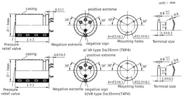 Figure 1-2 Four-pin electrolytic capacitor package
The four-pin package is the same as the two-pin package, except that the pins are changed from two to four.
When the size of snap-in electrolytic capacitors continues to increase based on the four-pin package, such as ≥35mm, a five-pin package is often required. Figure 1-3 shows a five-pin electrolytic capacitor package.
Among the four pins, the far end pin is the negative pole, the middle pin of the three prongs close to each other is the positive pole, and the remaining two pins are empty pins, which only serve to better fix the electrolytic capacitor.
The package in Figure 1-3a has one electrode pin for the positive and negative poles, and the rest are empty pins. The package in Figure 1-3b uses two pins for the positive and negative poles, and the remaining one pin is empty. Using two pins per electrode can enhance the current flow capacity of the electrolytic capacitor, which is common in large ripple current specifications.
The pins of four-pin and five-pin packaged electrolytic capacitors are “fool-proof” designed to eliminate the possibility of the electrolytic capacitor being plugged in reverse. However, there is a possibility of the polarity of the electrolytic capacitor being plugged in reverse, so it needs to be judged during assembly. Its positive and negative poles.
In order to eliminate the polarity reversal when two pins are assembled on a circuit board, it can be improved to a plug-in package, as shown in Figure 1-4.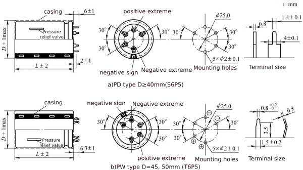 Figure 1-3 Five-pin electrolytic capacitor package
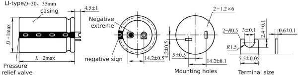 Figure 1-4 Electrolytic capacitor package with two blades
In Figure 1-4, the different directions of the positive and negative electrode inserts can completely eliminate the mis-insertion phenomenon of reverse polarity, achieving a “fool-proof” design. At the same time, the contact area between the insert and the circuit board is enlarged, which allows the electrolytic capacitor to be more firmly mounted on the circuit board, and the flowing current can also be increased.
When the snap-in electrolytic capacitor has a “slender” shape, in order to limit the height of the circuit board, it is often necessary to lay the snap-in electrolytic capacitor “flat”. In order to adapt to “lying flat” the snap-in electrolytic capacitor, the pins need to be “bent”, so there is a bent-pin electrolytic capacitor packaging form, as shown in Figure 1-5.
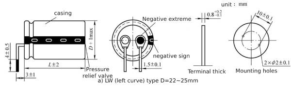
Figure 1-5 Bent-pin electrolytic capacitor packaging
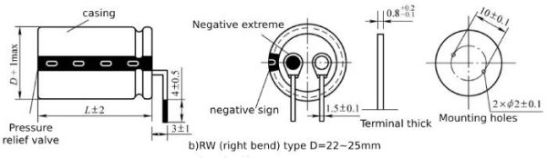
Figure 1-5 Angled pin electrolytic capacitor package (continued)
Since electrolytic capacitors have polarity, bent-pin electrolytic capacitors also need to be available in left-hand and right-hand forms.
In addition to pin-type packaging, medium and large electrolytic capacitors also have plug-type capacitors. Multiple plug-type pins can be used to better fix the electrolytic capacitor on the circuit board, as shown in Figure 1-6.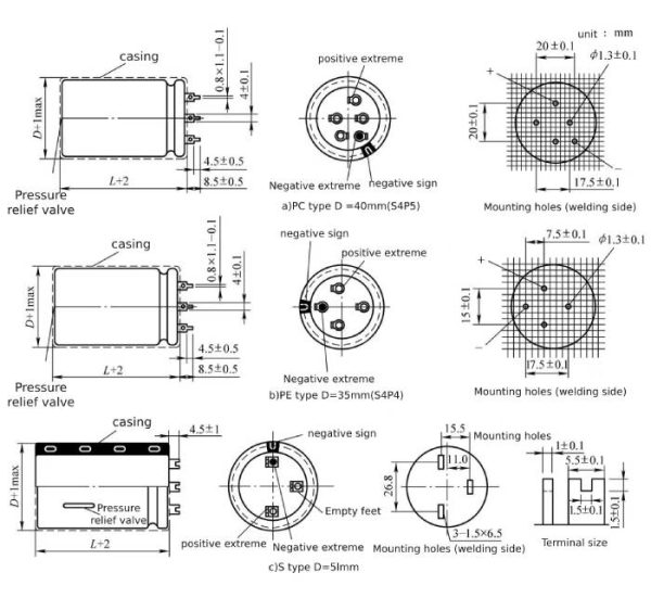 Figure 1-6 Multi-pin chip electrolytic capacitor package
The packaging method of the two pins has also been improved to a form in which the negative rivet leads to the two pins, which solves the “fool-proof” design of the two snap-in electrolytic capacitors and improves the firmness of the assembled circuit board, as shown in Figure 1- 7 shown.
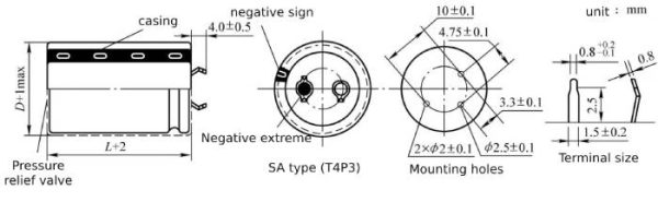 Figure 1-7 Two-terminal three-pin electrolytic capacitor package
If the electrolytic capacitor is not directly welded to the circuit board, the electrode form can also be made into a solder tab form, as shown in Figure 1-8.
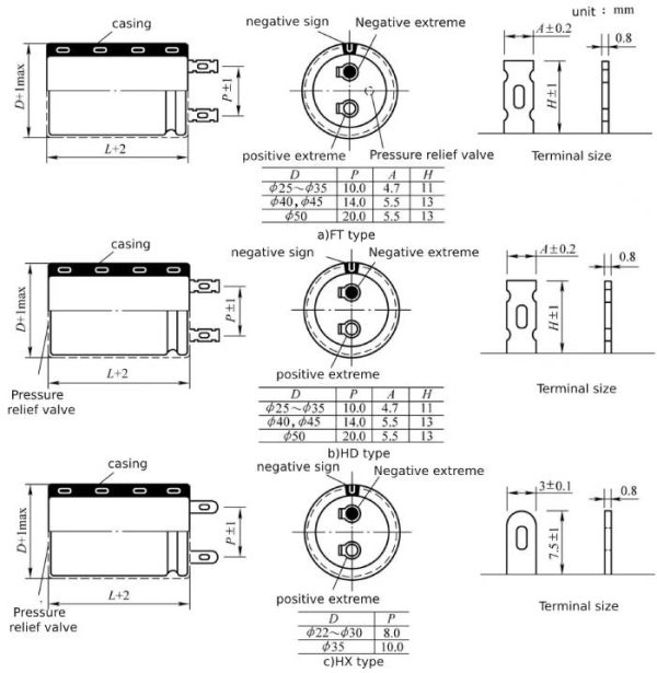 Figure 1-8 Soldering chip electrolytic capacitor package
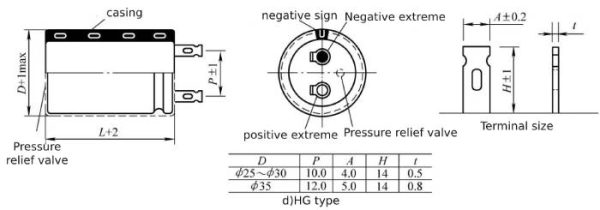 Figure 1-8 Solder-type electrolytic capacitor package (continued)
The electrolytic capacitor shown in Figure 1-8 only needs to weld the leads to the soldering lug of the electrolytic capacitor, which makes the assembly position of the electrolytic capacitor relatively flexible. However, this assembly method is not suitable for switching power converters.
If welding is inconvenient, the electrolytic capacitor shown in Figure 1-8 can also be connected using a plug-in connector.
2 CD293-Electrolytic capacitor data
CD293 is an 85℃/2000h universal snap-in aluminum electrolytic capacitor with a rated voltage of 10~500V and a capacitance of 100~82000μF.
The general data of CD293 snap-in aluminum electrolytic capacitors are shown in Table 1-1 ~ Table 1-4.
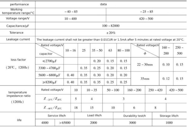
Table 1-1 Performance overview of CD293 snap-in aluminum electrolytic capacitors
 Continued
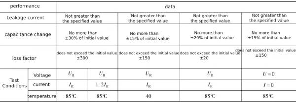
Note: All tests are completed within 0.5 to 24 hours after applying the rated voltage.
Table 1-2 Electrical parameters of CD293 snap-in aluminum electrolytic capacitor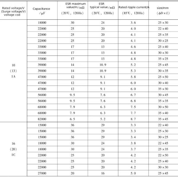
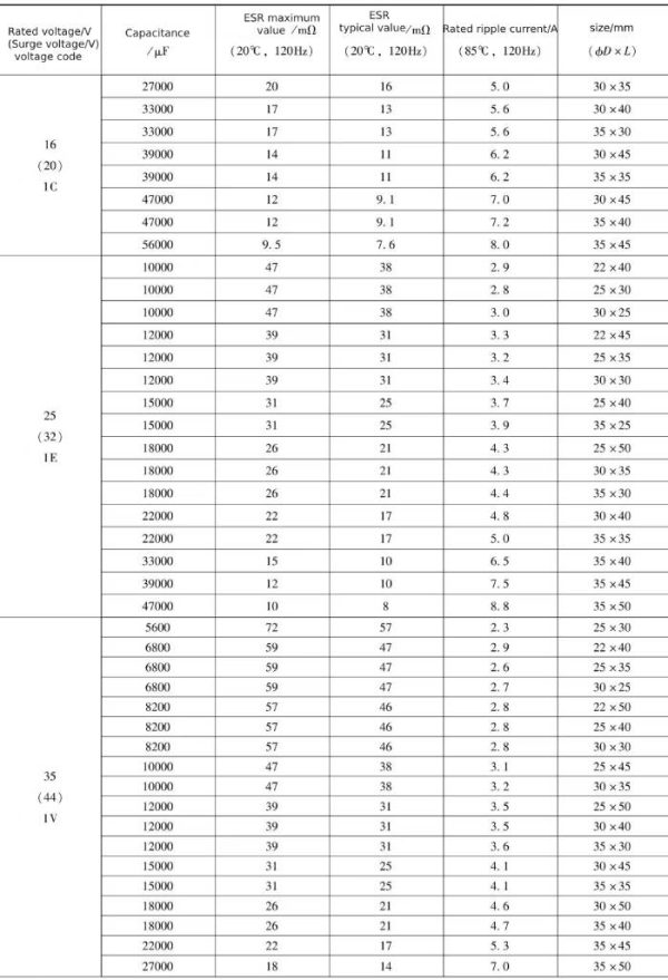
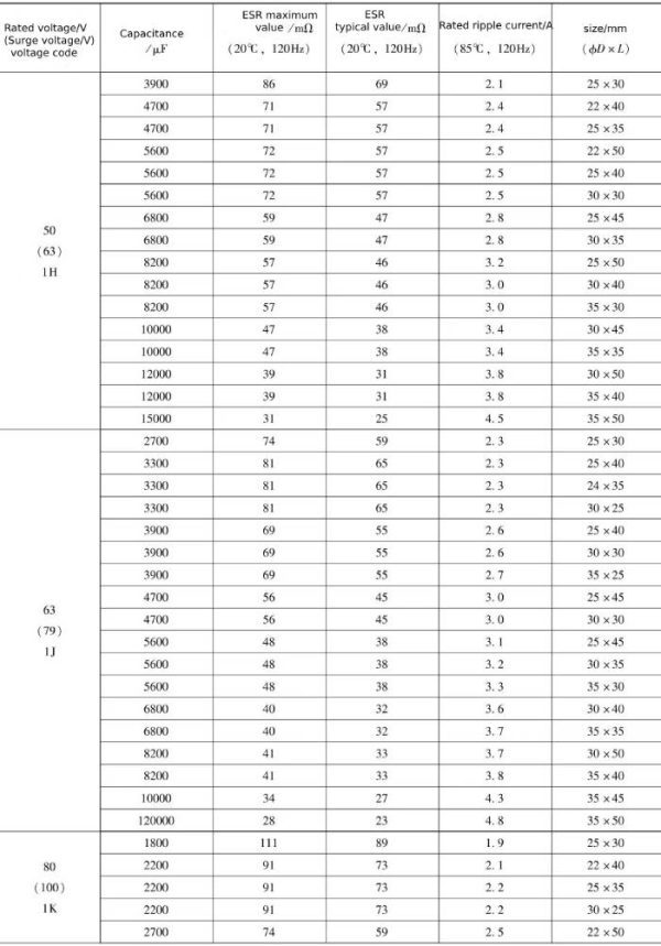
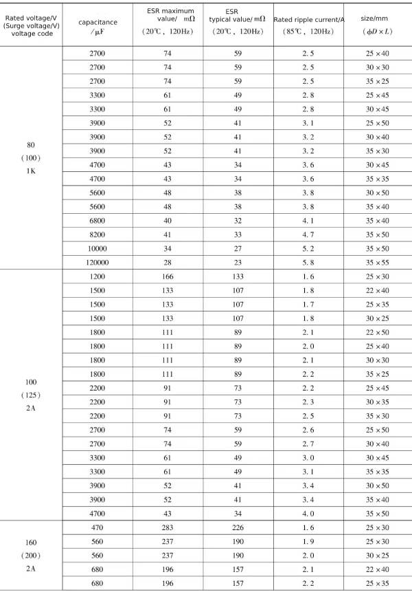
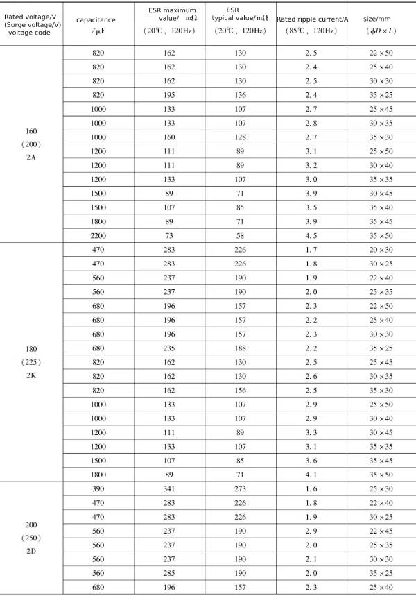
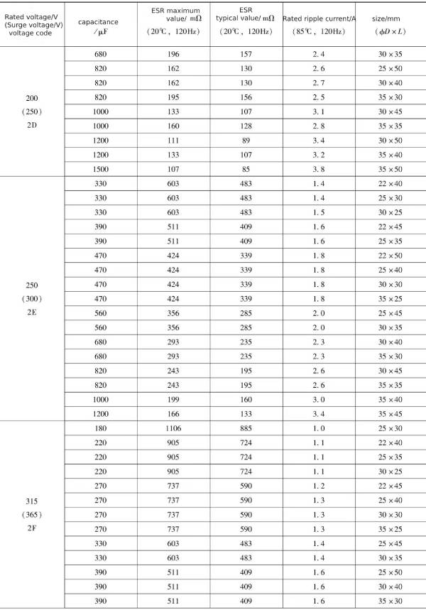
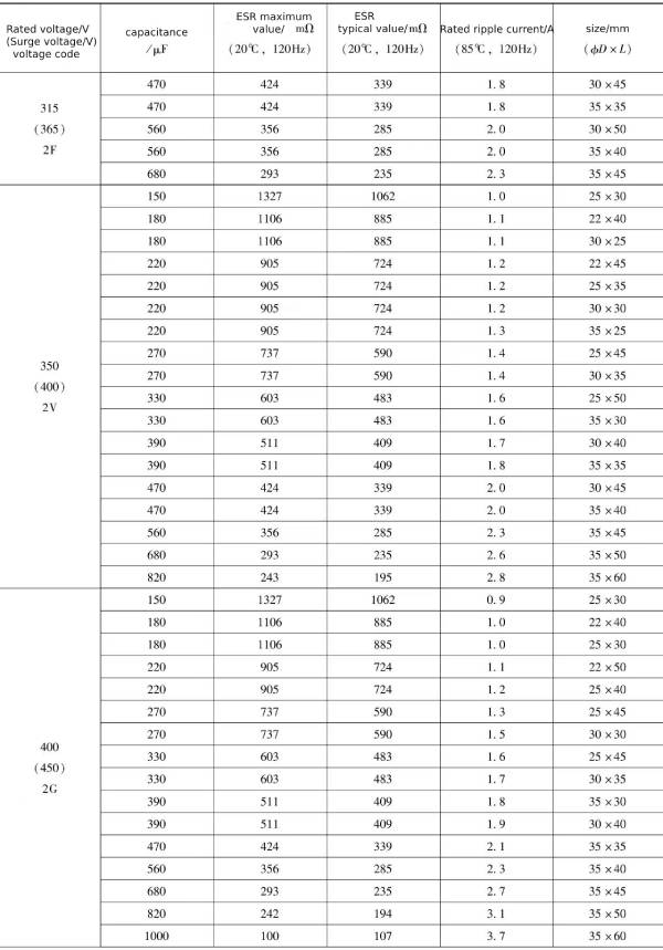
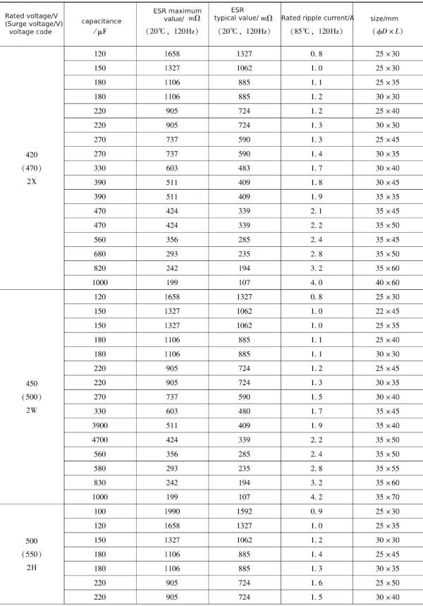
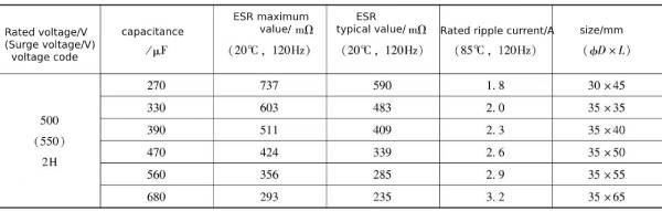 Table 1-3 Frequency conversion coefficient
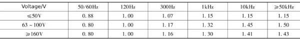 Table 1-4 Temperature conversion coefficient
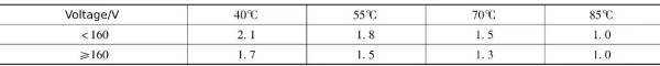
The relationship between CD293 BZ series life, ripple current and temperature is shown in Figure 1-9 and Figure 1-10.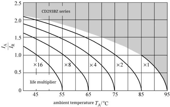 Figure 1-9 Lifetime curve of UR<160V specification
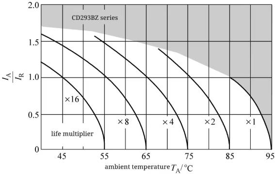 Figure 1-10 Lifetime curve of UR≥160V specification
3 CD29H series electrolytic capacitor data
CD29H is a 105℃/3000h, high ripple current snap-in electrolytic capacitor.
The general data of CD29H pin type aluminum electrolytic capacitors are shown in Table 1-5 ~ Table 1-8.
Table 1-5 Performance overview of CD29H snap-in aluminum electrolytic capacitors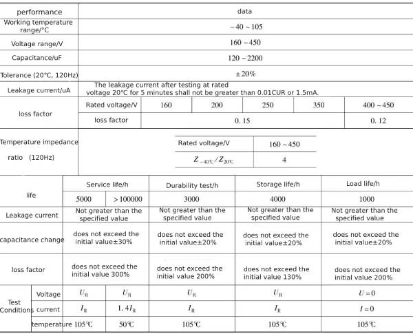
Note: All tests are completed within 0.5 to 24 hours after applying the rated voltage.
Table 1-6 Electrical parameters of CD29H type snap-in aluminum electrolytic capacitor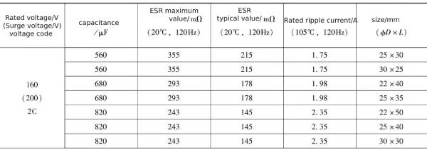 Continued
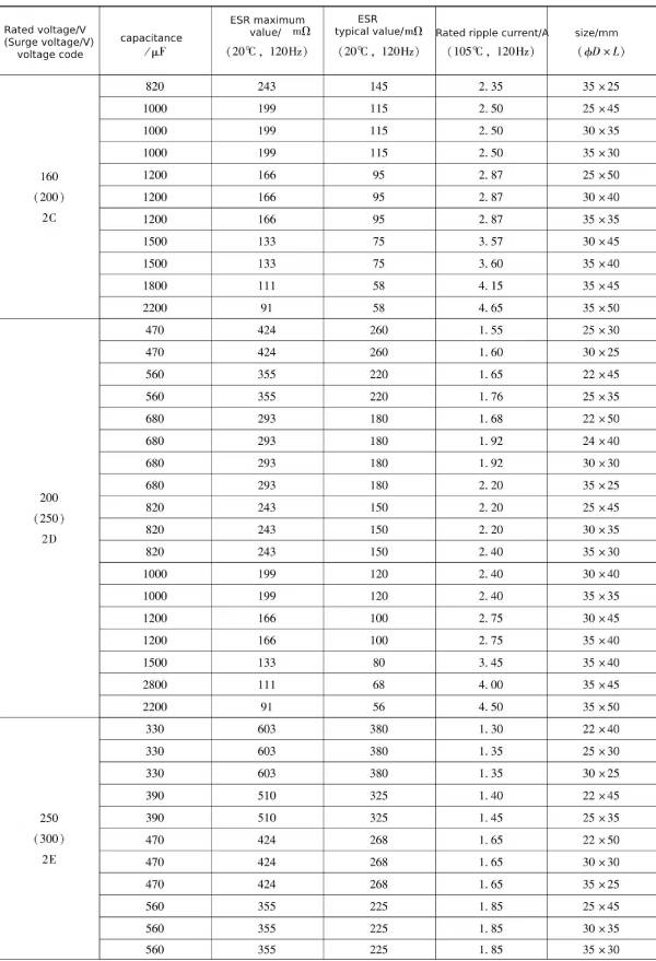 Continued
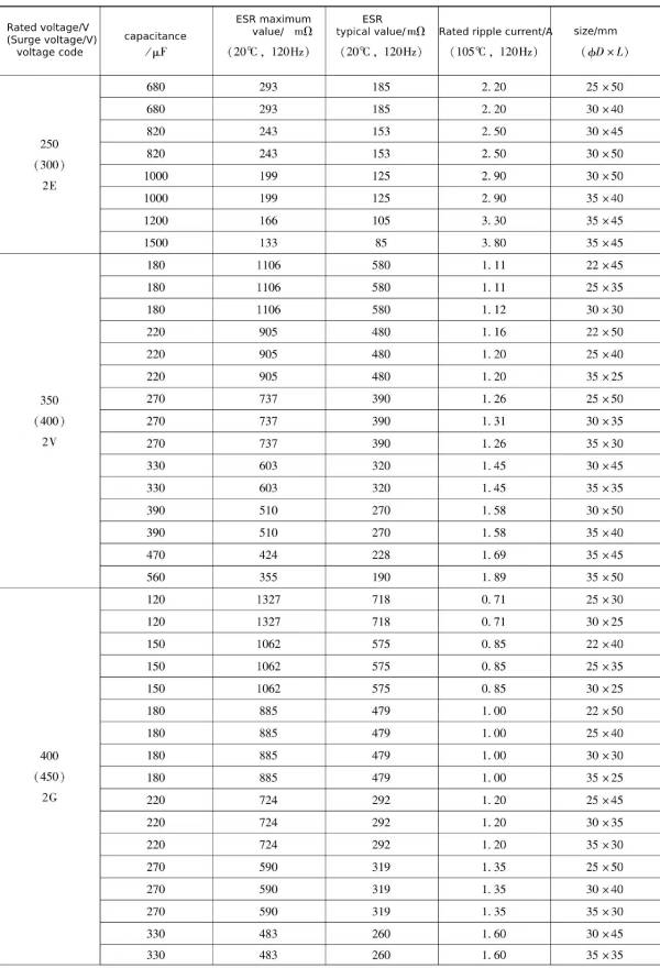 Continued
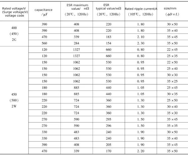 Table 1-7 Frequency conversion coefficient
![]() Table 1-8 Temperature conversion coefficient
Table 1-8 Temperature conversion coefficient![]()
The relationship between CD29H series life, ripple current and temperature is shown in Figure 1-11.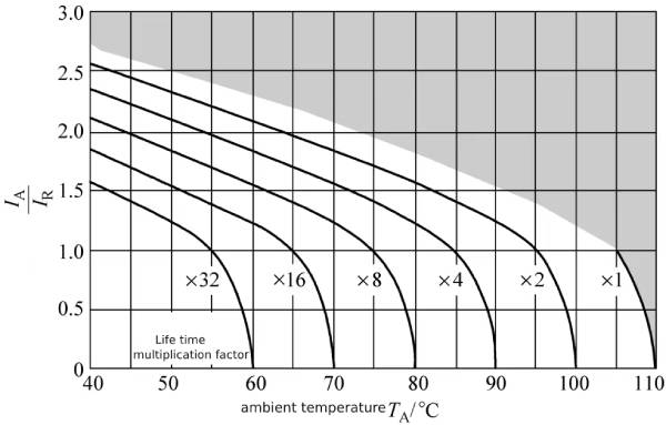 Figure 1-11 CD29H series life curve
4 CD29L series electrolytic capacitor data
The CD29L series is a snap-in electrolytic capacitor with large capacitance, high ripple current and full voltage series. The rated voltage range is 16~500V, and the maximum capacitance can reach 120000μF or 0.12F.
The performance overview of CD29L series snap-in aluminum electrolytic capacitors is shown in Table 1-9.
Table 1-9 Performance overview of CD29L series snap-in aluminum electrolytic capacitors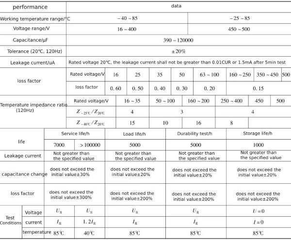
Note: All tests are completed within 0.5 to 24 hours after applying the rated voltage.
The ripple current frequency conversion coefficient of CD29L series snap-in aluminum electrolytic capacitors is shown in Table 1-10.
Table 1-10 CD29L series snap-in aluminum electrolytic capacitor ripple current frequency conversion coefficient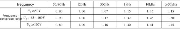
The ripple current and temperature conversion coefficients of CD29L series snap-in aluminum electrolytic capacitors are shown in Table 1-11.
Table 1-11 CD29L series snap-in aluminum electrolytic capacitor ripple current temperature conversion coefficient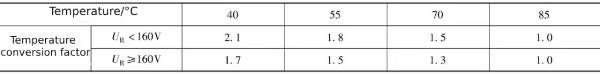
The detailed data of CD29L series snap-in aluminum electrolytic capacitors are shown in Table 1-12.
Table 1-12 Electrical parameters of CD29L series snap-in aluminum electrolytic capacitors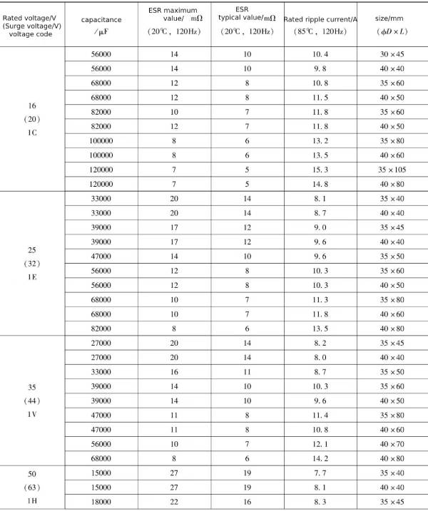 Continued
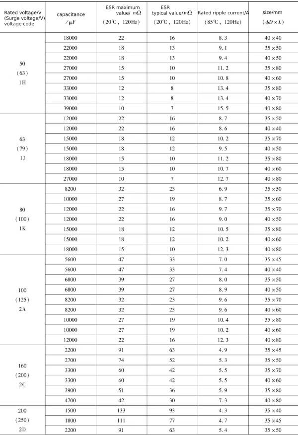 Continued
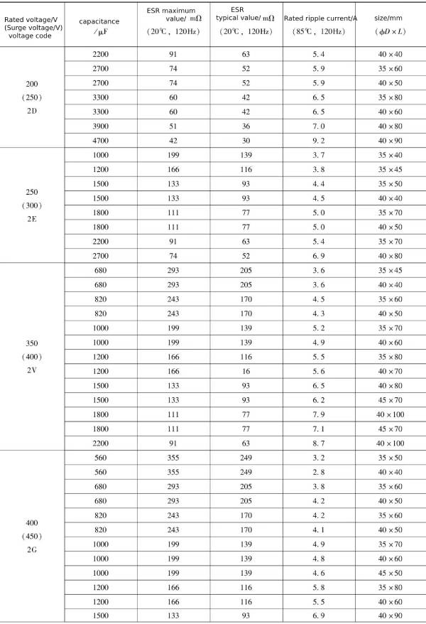 Continued
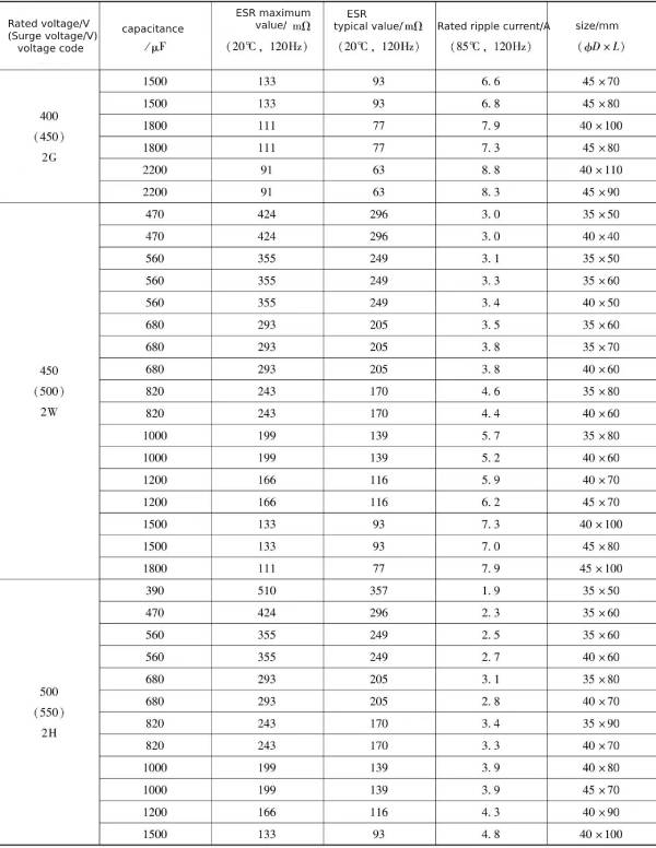
The CD29L series life curve is shown in Figure 1-12 and Figure 1-13.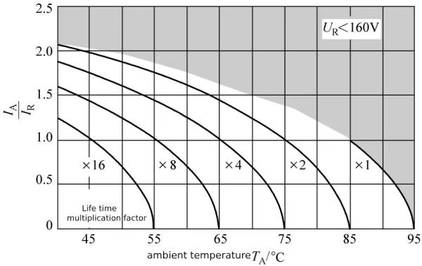 Figure 1-12 Life curve of CD29L series low voltage specifications
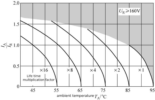 Figure 1-13 Life curve of CD29L series high voltage specifications
Summarize:
This article mainly talks about the packaging form of snap-in electrolytic capacitors and the data of CD293, CD29H, CD29L series snap-in electrolytic capacitors.To learn more about electrolytic capacitors please click:https://capacitorsfilm.com