Power capacitor are the most important equipment in AC and DC filters and shunt capacitor devices in DC converter stations. Understanding and mastering the production process of capacitors has certain practical significance for us to better maintain equipment and deal with faults during equipment operation.
I. Overview
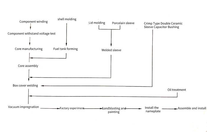
🌱Capacitors have strict production processes in equipment manufacturers, and control of environmental cleanliness is very strict in the production process. Process control is very important to ensure the quality of capacitors. Strict process is the basis of capacitor production and manufacturing. It runs through the whole process of capacitor production and production. It is the best way to realize product design and ensure product quality under certain production conditions. important means. As shown in Figure 1-38, it is the general process flow of power capacitor production in workshop.
2. Manufacturing process of high voltage shunt capacitors
1. Production of shell body, bottom and cover
💐(1) The lower parts and stamping of metal parts; the materials are processed and formed by cutting, punching, stretching, bending and other methods. These include shells, bottoms, covers, hanging climbs, etc.
🌷(2) Welding of the outer shell of the fuel tank; the longitudinal seam welding of the shell is realized by argon arc welding, and the shell body and the bottom are welded and formed to be called the fuel tank.
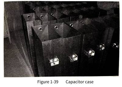
🌹(3) Production of the box cover: The integrated sleeve is crimped, and the sleeve is welded on the cover with an automatic argon arc welding circular seam welding machine, so that the box cover of the capacitor is completed, as shown in Figure 1-39.
2. Capacitor core manufacturing
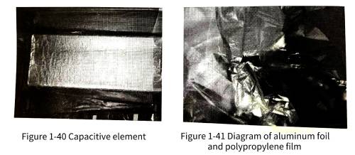
🌺The capacitor core is composed of components (components composed of electrodes separated by dielectrics and aluminum foil), insulating parts, and various clamping parts. The winding of components (the process of winding dielectric materials and electrode materials into components according to certain combination requirements) is completed in a clean room, and the production process has strict requirements on the chemical level and indoor temperature. It can only be produced when the process conditions are met. Using a rolling machine, the aluminum foil with a thickness of 6um and the double-sided polypropylene roughened film (thickness of 10.5∽18um) are rolled according to the method of 6-layer film and 2-layer aluminum foil. , with 3 layers of film between each foil. The capacitor element is shown in Figure 1-40, and the aluminum foil and polypropylene film are shown in Figure 1-41.
3. Component withstand voltage test
🌸After each component is successfully rolled, the pressure resistance of the component is automatically tested by the component pressure machine, and the unqualified components are automatically removed to ensure the quality of the product.
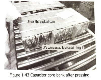
4. Core pressing
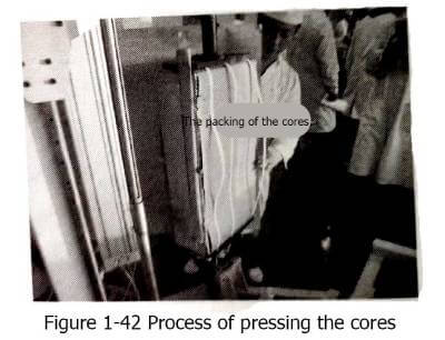
🌼According to the core assembly drawing, place the splint, components, gaskets, connectors and other components in sequence. Using the press, press the core to a certain height according to the compression coefficient, and then put on the hoop or binding and packing tape, and the core loading is completed. Figure 1-42 shows the core pressing process, Figure 1 -43 is the capacitor core group that has been press-fitted.
5. Core welding
🌻 The process of welding the components of the core according to certain electrical combination requirements.
6. Core outsourcing
🌞 This process is realized by the outsourcing machine of the core.
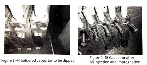
7. Packing
🌝 Put the wrapped core (core group) into the fuel tank and weld the tank cover. Put the body into the fuel tank, connect the lead of the body to the lead of the cover, and use a profiled argon arc welding machine to complete the welding of the tank cover. The welded capacitor to be dipped is shown in Figure 1-44.
3. Vacuum drying and dipping of capacitors
1. Purification of insulating oil
🌟This process is mainly used to remove impurities, moisture and gas in the impregnating agent, making it more pure, and must make its electrical and chemical properties meet the performance requirements of capacitors. There are two kinds of insulating oils commonly used in my country: S oil PXE phenyl xylyl ethane, C101-benzyl toluene M/DBT.
2. Vacuum impregnation treatment of high voltage shunt capacitors
✨The vacuum drying and impregnation process is divided into several stages, such as ① heating, ② low vacuum, ③ high vacuum, ④ oil injection, and ⑤ impregnation.
4. Factory test and follow-up work of high-voltage capacitor products
1. Basic requirements of the test
⚡️The test of high-voltage capacitors is an investigation of the final result of the entire capacitor production. In order to ensure the accuracy and reliability of the test, all tests should be carried out under certain conditions, and the test environment conditions should be paid attention to and records should be made. There are two types of test environmental conditions, one is artificial environment, in this case, the product standards are generally specified; the other is natural environment conditions, in this case, the test conditions should generally follow the following 3 rule;
(1) The ambient temperature should be within the scope of the standard and agreement;
(2) There should be no significant difference between the temperature of the test product and the environment;
(3) The test sample is considered to be the same as the ambient air temperature after it has been placed in a constant ambient air temperature for an appropriate period of time in the state of no electricity.
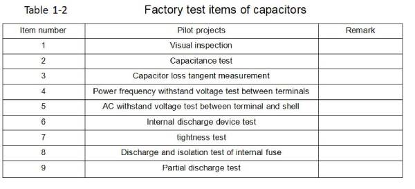
3.Factory test of capacitors
☀️The purpose of the power capacitor factory test is to check the defects in the manufacture and measure whether the indicators of the capacitor meet the requirements of the standard and technical agreement. Test sequence: Capacitance measurement and loss tangent measurement test should be carried out after the power frequency withstand voltage test, and the sequence of other tests may not be specified. The factory test items are shown in Table 1-2.
4.Standards to follow for power capacitor test
🌈The power capacitor test should comply with the following standards: GB/T11024.1-2010 (parallel capacitors for AC power systems with a nominal voltage above 1000V Part 1: General), GB/T11024.2-2001 (Nominal voltage above 1kv) The AC power system has shunt capacitors Part 2: Endurance test), GB/T 11024.4–2001 (Shunt capacitors for AC power systems with a nominal voltage above 1kV Part 4: Internal fuses), GB/T20994-2007 ( Shunt capacitors and AC filter capacitors for HVDC transmission systems), DL/T 840-2003 (Technical conditions for the use of high voltage shunt capacitors)
4. Introduction to the factory test method
💥(1)Capacitance measurement of capacitors. Capacitance measurement is a must-test item for capacitors. Capacitance value is the basic characteristic quantity of capacitors, which is used to calculate reactive output capacity.
🍓Capacitance measurement methods: ①Voltage and ammeter method; ②Dual voltmeter method; ③Bridge method; ④Capacitance meter direct measurement method.
🍒Under the standard ambient temperature, the first three methods are generally used to measure the capacitance value at the factory, and the fourth method is generally adopted on site.
🍑(2)Measurement of capacitor loss tangent. The purpose of measurement of loss tangent value: to check whether there are local defects such as insulation deterioration inside the capacitor. In addition to the dielectric loss, the loss of the capacitor also includes the dielectric loss of the pole-to-shell insulation, the loss of the inner conductive electrode plate, the connecting wire and the inner fuse, and also includes the partial discharge loss.
🍍Measurement methods of capacitor loss: ① current balance method: ② wattmeter method; ③ AC bridge method (positive wiring, reverse wiring measurement method).
Factors Affecting Capacitor Loss:
1) The degree of contamination on the surface of the capacitor porcelain sleeve;
2) Electric field interference and magnetic field interference;
3) The setting position and length of the bridge leads;
4) The influence of temperature and humidity of the test environment;
5) Influence of high voltage standard capacitors;
6) The influence of stray capacitance on the loss of the test product.
🥝(3)Power frequency AC withstand voltage test of capacitors. The power frequency AC withstand voltage test of capacitors is divided into: power frequency withstand voltage test between terminals and power frequency withstand voltage test between terminals and shell. Purpose of AC withstand voltage test: AC withstand voltage test is the most stringent, effective and direct test method to identify the dielectric strength of capacitor products, and is also an important means to ensure the insulation level of capacitors and avoid internal failures of capacitors.
🍭In the AC withstand voltage test, attention should be paid to the boosting speed. The withstand voltage test of the capacitor should start from zero potential and increase the voltage evenly to ensure accurate readings on the meter. When it rises to 75% of the voltage, it will rise to 100% voltage at a rate of 2% per second. After the time has elapsed, gradually reduce the voltage to zero, and then cut off the power supply. It is never allowed to suddenly pressurize or cut off the power supply suddenly when the voltage is higher, so as to avoid damaging temporary overvoltage on the tested product.
🍬(4) Check the internal discharge device of the capacitor. Most of the power capacitor are equipped with discharge devices. Their function is to release the charge to below the specified level within a specified time after the product is disconnected from the power supply, so that the terminal voltage of the power capacitor is reduced to a safe voltage. Below 75 V. Test methods include DC charging method and resistance measurement method.
🥙(5) Discharge test of the fuse in the capacitor. The purpose of the test is to assess the firmness of the connection between the inner fuse and the component. The test is the content of the factory test.
🧆Test method: apply DC 1.7 Ω to the capacitor terminals, discharge through the shortest possible loop, and measure the capacity of the capacitor before and after the test.
🌮Judgment basis: before and after the test, the difference in capacitance change is less than the change caused by a fuse blowing. In the following chapters of this book, we will introduce the specific calculation of the capacitance change of a fuse blown.
🍩(6) Isolation test of the fuse inside the capacitor. The purpose of the test is to evaluate whether the internal fuse can reliably isolate the damaged components in the capacitor.
🍡Test method, the test is carried out at 0.9 and 2.2 voltages, respectively, using the mechanical puncture method. After the test, DC 3.5 was applied between the blown fuses for 10s.
🍸Judgment basis: Before and after the test, measure the capacitance to prove that the fuse has blown, and check the withstand voltage of the fracture and other parts.
🍹(7) Partial discharge test of power capacitor. Test purpose: Assessing the dielectric insulation performance of the capacitor is an effective supplement to the withstand voltage test. It is a non-destructive test and an important means to test the insulation weakness of the capacitor and correct the improper use of design, manufacturing process and materials.
🥗Compared with the AC withstand voltage test, the partial discharge test is a non-destructive test. By measuring the partial discharge of the high-voltage capacitor product, the insulation quality of the product can be determined without damaging the insulation performance. The local hair test has high sensitivity. Through the test, the weak link in the insulation can be found, and the error in the design and manufacturing process and the improper use of the material can be prevented. It is an important method to identify the insulation reliability of the product.
🥯Partial discharge test can make up for the lack of withstand voltage test. Partial discharge tracking test is carried out for all products that leave the factory, and the test results of partial discharge are recorded and analyzed. The insulation weakness in the product can be found out in a timely and accurate manner, and appropriate measures can be taken to make it happen. The factory product can operate safely.
🧀Test methods: non-electrical and electrical. Non-electrical measurement methods include noise detection method, light wave detection method, thermal detection method and air pressure detection method. Electric measurement methods include radio interference measurement method, high-frequency pulse current measurement method, pulse polarity identification measurement method. The approach may be different, but the purpose is the same.
5. Follow-up work
🥞After the above tests have verified that the capacitor is qualified, the follow-up work is mainly sandblasting, painting, and spraying protective paint on the metal shell of the capacitor to improve the anti-corrosion performance and appearance quality of the capacitor.
Our website:www.xuanxcapacitors.com/xuansncapacitor.com/solidcapacitor.com/xuanxcapacitors.ru