1 Working status of electrolytic capacitors—The role of electrolytic capacitors in flyback switching power supplies
1.1 AC input power filter circuit
Working status of electrolytic capacitors – low-power switching power supplies are widely used, requiring the cost to be as cheap as possible, the components to be as few as possible, and the size to be as small as possible. Among various isolated (OFF Line) switching power supply circuit topologies, the flyback switching power supply circuit is the simplest and the lowest cost. Therefore, most of the switching power supplies with output power below 64W use flyback circuit topology.
The general principle block diagram of a switching power supply is shown in Figure 1-1.
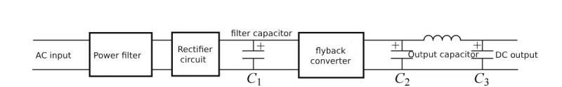
Figure 1-1 General principle block diagram of switching power supply
In Figure 1-1, filter capacitor C1and output capacitors C2 and C3are all electrolytic capacitors.
Usually, the switching power supply must have an AC input power filter circuit to meet EMC (electromagnetic compatibility) requirements, so as not to interfere with the power grid and other electrical equipment, nor to be interfered by the AC power grid and other equipment. This AC input power supply filter circuit consists of a varistor, X capacitor, common mode inductor, and Y capacitor. The circuit is shown in Figure 1-2.
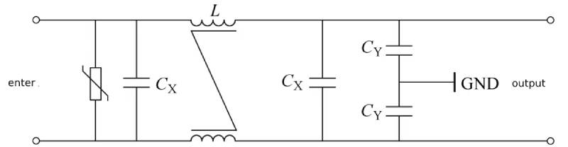
Figure 1-2 AC input power filter circuit of switching power supply
In addition to allowing the switching power supply to meet EMC requirements, the circuit in Figure 1-2 has no effect on the functional realization of the switching power supply. So, can the AC input power filter circuit, which takes up both space and cost, be omitted under certain conditions? This is the dream of switching power supply manufacturers.
This issue will be explained in detail later.
Working status of electrolytic capacitors—the above is the analysis of AC input power filter circuit
1.2 The role of electrolytic capacitors in switching power supplies
Working status of electrolytic capacitors – There are two major passive components in switching power supplies: capacitors and inductors/transformers. These two types of passive components greatly affect the performance and cost of switching power supplies.
Since switching power supplies all use AC mains direct rectification/filtering, the mains rectification and filter capacitors are high-voltage electrolytic capacitors, and the rated voltage is usually 400V.
The mains rectifier filter capacitor rectifies the mains power and outputs a smoothing voltage within the allowable range, so it is also called a “smoothing capacitor”. The rectified output voltage waveform without capacitor filtering is shown in Figure 1-3, and the rectified output voltage waveform after capacitor filtering is shown in Figure 1-4.
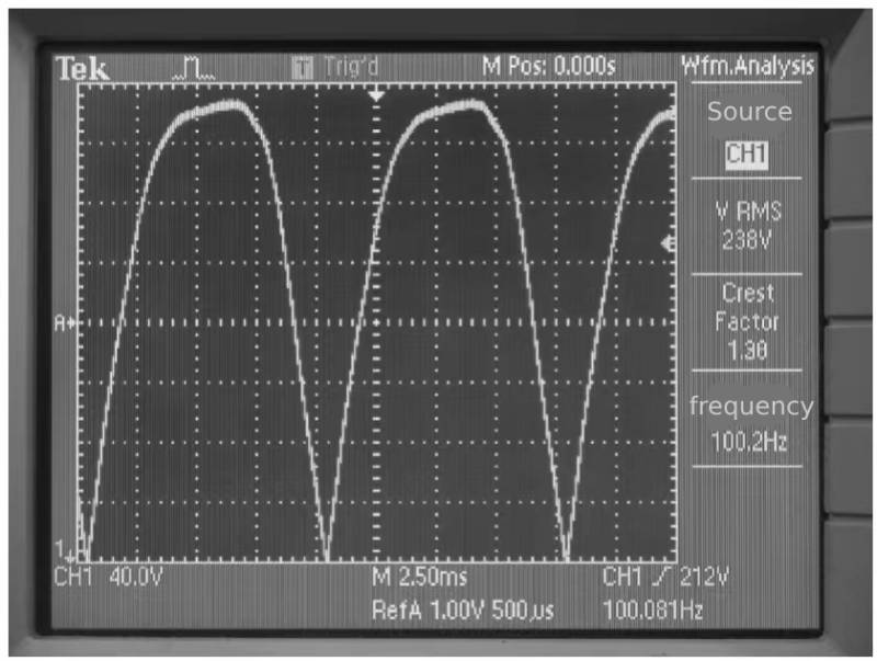
Figure 1-3 Rectified output voltage waveform without capacitor filtering

Figure 1-4 Rectified output voltage waveform filtered by capacitor
Comparing Figure 1-3 and Figure 1-4, we can see the “smoothing” effect of the capacitor on the rectified output voltage. Since it is power frequency (50Hz or 60Hz) AC rectification, smoothing the rectified output voltage to a smoothness level that can be used in the subsequent stage of the switching power supply requires a capacitor with a larger capacitance, so electrolytic capacitors become the first choice.
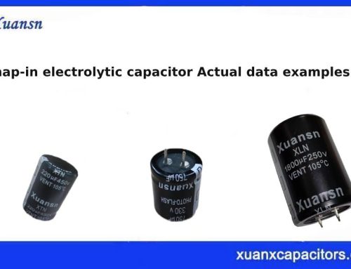
The electrolytic capacitor in the small power switching power supply is shown in Figure 1-5.
From packaging and cost considerations, the mains rectification and filter capacitors of small-power switching power supplies all use lead-pin electrolytic capacitors, as shown in Figures 1-6 and 1-7.
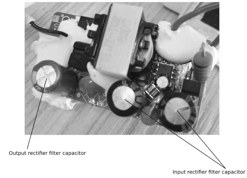
Figure 1-5 Electrolytic capacitors in small power switching power supplies
 Figure 1-6 High-voltage lead-pin electrolytic capacitor
 Figure 1-7 Low-voltage lead-pin electrolytic capacitor
This type of lead-pin electrolytic capacitor can be soldered directly to the PCB through the reflow soldering process. Compared with pin-type electrolytic capacitors, the biggest feature is its low cost.
Working status of electrolytic capacitors—The above is an analysis of the role of electrolytic capacitors in switching power supplies.
1.3 Solutions and disadvantages without varistor, X capacitor and common mode inductor
The AC input power supply filter circuit in Figure 1-2 is used to suppress electromagnetic interference from the AC power grid, especially transient overvoltage, lightning strikes, etc. For this purpose, a varistor, X capacitor, and common mode inductor are added to the circuit. If these circuits and components unrelated to power conversion can be omitted, the cost and size of the power supply can be significantly reduced. So to what components are the original functions of the AC input power supply filter circuit, especially the transient overvoltage or lightning strike functions, transferred?
Most switching power supplies below 30W do not have AC filter circuits, which can save space and reduce costs. The AC filtering function is transferred to the filter capacitor (electrolytic capacitor) after the rectifier. In the design example (5.6W) using the Tiny Switch switching power supply chip launched by PI Company in 1998, the varistor, X capacitor, and common mode inductor were omitted, as shown in Figure 1-8.
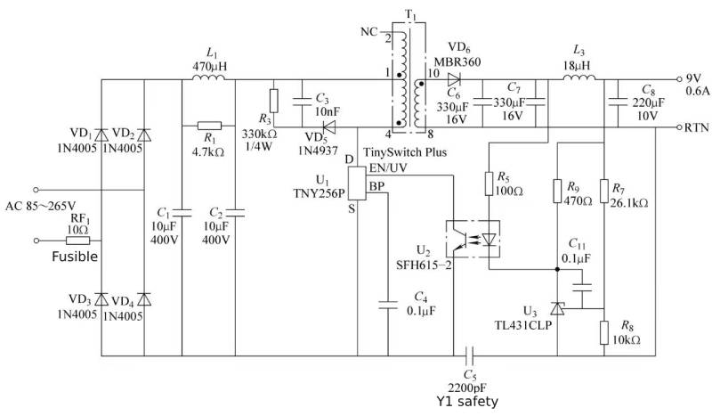 Figure 1-8 Switching power supply input stage without power filter circuit
The circuit shown in Figure 1-8 is quoted from the application example circuit of the Tiny256 data sheet in the PI company document. In the figure, two electrolytic capacitors and a differential mode inductor are selected to form a π-type filter circuit to meet EMC test requirements. Since the differential mode inductor is connected in series between the two electrolytic capacitors, the functions achieved by the two electrolytic capacitors will be different. The front stage needs to meet the lightning strike or transient overvoltage withstand capability and the smooth rectified output voltage function after rectification. The rear stage mainly flows through the ripple current at the switching frequency.
Through such circuit simplification, the circuit cost can be significantly reduced and the volume can be reduced by 20% to 30%. However, the price paid for this is that the varistor and X capacitor that originally completed the lightning strike resistance have been removed. The lightning strike resistance function needs to be realized by electrolytic capacitors, that is, the electrolytic capacitors C1 and C2 in the circuit shown in Figure 9-8 are required to have lightning strike resistance functions. .
With the strong request of power engineers and the unremitting efforts of electrolytic capacitor R&D engineers, it has gradually been realized that small electrolytic capacitors with a rated voltage of 400V can pass the lightning test of 1kV, 1.5kV, 2kV, 2.5kV, and 3kV, making the 30W made in my country The following switching power supplies can pass EMC and lightning tests without varistor, X capacitor and common mode inductor.
From the perspective of the characteristics of electrolytic capacitors themselves, this lightning strike resistance is unfair to electrolytic capacitors. The reason is simple. For an electrolytic capacitor with a rated voltage of 400V, the formation voltage of the formation foil is generally 530V, which has exceeded the formation voltage of the positive electrode foil and the flash voltage of the electrolyte. When testing the 3kV lightning strike voltage, the positive foil of the electrolytic capacitor will inevitably enter the formation state, and the actual peak voltage of the electrolytic capacitor can reach nearly 700V!
In this state, the withstand voltage of the electrolytic capacitor exists in the creepage distance between the capacitor paper and the two electrodes. If the capacitor paper has insufficient withstand voltage or the creepage distance between the electrodes is insufficient, sparking will occur inside the electrolytic capacitor. And then breakdown the electrolytic capacitor. If the capacitor paper withstands a good voltage and the creepage distance between the two electrodes is sufficient, the electrolytic capacitor can withstand the violent formation process without causing breakdown and ignition. However, since the electrolytic capacitor is formed into a pattern, a large amount of gas and heat will be generated. If the electrolytic capacitor is not designed well, it is likely to have a convex bottom.
If the electrolytic capacitor is well designed, it can pass the lightning test. Relatively speaking, such technical requirements are unfair to electrolytic capacitors. Because a film capacitor with a rated voltage of 400V will never pass the 3kV lightning test, at least X capacitors must be used to withstand the instantaneous overvoltage of 2.5kV.
This method also poses a threat to the rectifier bridge and subsequent switch tubes.
The transient overvoltage process can produce such a high formation voltage that may be a threat to the rectifier bridge in front of the electrolytic capacitor. General rectifier bridges do not have avalanche breakdown resistance. If the rectifier bridge withstand voltage is only 600V, the rectifier bridge may be irreversibly damaged. At the same time, the withstand voltage of the subsequent switching tube (or MOSFET built into the IC) is generally 600 to 650V, and overvoltage breakdown will also occur, and the electrolytic capacitor will also be broken down. Therefore, it is common to see breakdown of rectifier bridges and switching tubes, convex bottoms of electrolytic capacitors, and blown fuses. The essence of this fault is that the circuit design is unreasonable in principle, not the problem of the electrolytic capacitor. It is wrong to attribute the problem to the quality of the electrolytic capacitor.
The reason is that the original AC power filter circuit uses a varistor and X capacitor to block transient overvoltage and lightning overvoltage in front of the rectifier bridge. Then the terminal voltage of the rectifier bridge is the voltage value of the electrolytic capacitor, which generally does not exceed 400V; Similarly, the switching tube will not be broken down by instantaneous overvoltage or lightning overvoltage.
To sum up, in order to reduce the cost of the switching power supply, the AC power supply filter circuit is omitted, allowing the electrolytic capacitor to withstand transient overvoltage and lightning overvoltage, while also causing the rectifier bridge and switching tube to withstand the “formed” overvoltage.
Working status of electrolytic capacitors—the above is an analysis of solutions and disadvantages without varistor, X capacitor and common mode inductor
1.4 The special role of electrolytic capacitors in flyback switching power supplies below 30W
Circuits without varistor, X capacitor, and common mode inductor can be used in switching power supply solutions below 30W. Figure 1-9 shows a multi-output switching power supply circuit with a power of 17W.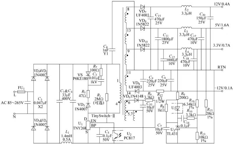
Figure 1-9 17W multi-output switching power supply circuit
The circuit shown in Figure 1-9 is quoted from PI Company’s 2002 Design Idea DI-33, which is a multi-output switching power supply with a peak power of 17W.
In China, this kind of switching power supply design scheme from 20 years ago is no longer suitable for the design of low-power switching power supply. my country’s small-power switching power supplies already have circuit topology and control modes with better performance. This book gives examples here to illustrate that solutions without varistor, X capacitor, and common mode inductor entered my country 20 years ago and were carried forward by our country’s power engineers and became the “standard configuration” of switching power supplies below 30W.
Through the unremitting efforts of Chinese power engineers, the switching power supply solution without AC filter circuit can pass the EMC test, but there is still a hidden danger that lightning test or actual transient overvoltage may breakdown the rectifier bridge and switching tube.
In addition to adding lightning resistance, the input rectification and filtering capacitors must also implement conventional rectification and filtering functions.
Since the input voltage is a full-voltage input type, it needs to adapt to the filtering requirements when the minimum AC voltage is 85V. For both TOP-Switch and Tiny-Switch, it is necessary to set an output power of 1W corresponding to a 3μF capacitance, so an output power of 17W requires a 51μF capacitance. , so choose two 33μF capacitors. Since electrolytic capacitors do not have power factor correction function, the rated voltage is 400V.
The current distribution relationship between electrolytic capacitors C1 and C2 is as follows.
Since there is an inductor connected between C1 and C2, the current is no longer shared equally between them.
First look at the current distribution of the switching frequency. Since the switching frequency is about 130kHz, the capacitive reactance corresponding to the 33μF capacitor is

A 33μF capacitor has an ESR of approximately 1Ω at 100kHz.
The inductive reactance of the 1.4mH inductor is
![]()
Obviously, due to the role of L1, the switching frequency ripple current from the flyback switching power supply is basically not diverted to C1.
Look at the 100Hz ripple current distribution after rectification.
The corresponding capacitive reactance of a 33μF capacitor is

The inductive reactance of the 1.4mH inductor is
![]()
It can be seen that the inductive reactance of L1 is much lower than the capacitive reactance of C1 and C2, so in terms of 100Hz ripple current distribution, L1 has little impact on the current sharing of C1 and C2.
To sum up, C1 only bears half of the 100Hz ripple current, and the other half is borne by C2.
C2 not only has to bear half of the 100Hz ripple current, but also the entire ripple current from the flyback converter. Relatively speaking, C2 will likely overcurrent. In actual cases, it will be found that the proportion of early failure of C2 is higher than that of C1.
Working status of electrolytic capacitors—the above is an analysis of the special role of electrolytic capacitors in flyback switching power supplies below 30W
2 Working status of electrolytic capacitors in full-voltage flyback switching power supply
2.1 Selection of rated voltage of rectifier and filter capacitors
Full-voltage switching power supply refers to a switching power supply suitable for all single-phase low-voltage power supply systems. The frequency is 50Hz or 60Hz, and the voltage ranges from the lowest voltage of 110V voltage level 85V to the highest voltage of 220V voltage level 265V. This requires the rectifier filter circuit to meet the 265V rms input voltage requirement in terms of voltage performance, as well as the circuit requirements under the minimum voltage 85V rms input condition and the ripple voltage requirements of the rectified output voltage.
The peak voltage corresponding to the effective value of 265V is 370V, and the corresponding rectifier bridge withstand voltage is at least 370V. Considering the transient overvoltage of the AC power grid, the rectifier bridge withstand voltage must be at least 600V. The theoretical maximum value of the rectified output voltage is 370V. You can choose an electrolytic capacitor with a rated voltage of 375V. Considering that voltage derating can significantly improve the service life, domestic electrolytic capacitors with a rated voltage of 400V are basically selected.
In switching power supplies, most rectifier and filter circuits use direct rectification of AC power to obtain the simplest circuit and the lowest cost.
For AC 220V voltage level or 85-265V global voltage level, direct rectification and filtering requires a rectifier filter capacitor with a withstand voltage of 400V. If it is power factor correction, a withstand voltage of 450V is required. Its service life should be at least 85℃/2000h or 105℃/2000h. If long life is required, you can choose a product with longer hours.
Working status of electrolytic capacitors – the above is an analysis of the selection of rated voltage of rectifier and filter capacitors
2.2 Minimum capacitance required for rectifier and filter capacitors
Rectifier and filter capacitors are used to limit the rectifier and filter output voltage ripple. The correct selection of capacitance is very important. Usually, the capacitance of the rectifier filter capacitor is selected to be greater than or equal to 1μF/W according to the output power when the input voltage is 220V±20%, and according to the output power when the input voltage is 85~265V (110V-20%~220V+20%) Select greater than or equal to 3μF/W.
The value of the capacitance of the rectifier filter capacitor is based on: at the lowest value of the AC input of 220V±20% and the AC input of 85~265V, the lowest value of the rectified output voltage is not less than 200V and 90V respectively, and the voltage difference is 40V and 90V respectively. 25V. In each half power cycle (10ms), the rectifier conducts electricity for about 2ms, and the remaining 8ms is the discharge time of the rectifier filter capacitor to provide full current to the load, that is
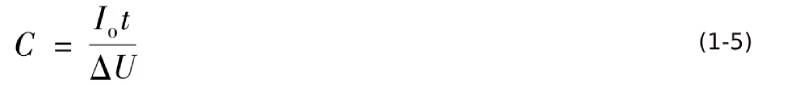
In the formula, Io is the average value of the output current; t is the discharge time of the filter capacitor; ΔU is the voltage difference.
When 220V × (1-20%) = 176V AC input, the corresponding average rectifier filter output voltage is about 200V. The required capacitance when the voltage fluctuates ±20% is
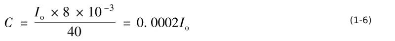
The corresponding output power is
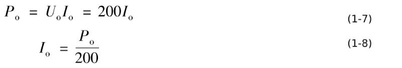
Substitute equation (1-8) into equation (1-6) to get

That is 1μF/W.
85~265V AC input
The corresponding output power is
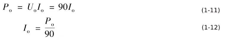
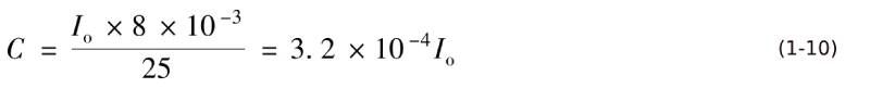
Substitute equation (1-12) into equation (1-10) to get

That is 3.6μF/W.
If in each half power cycle (10ms), the rectifier conducts time for about 3ms, and the remaining 7ms is the rectifier filter capacitor discharge time, providing full current to the load, then the rectifier filter capacitor capacity is 0.88μF/W and 3.15μF/W.
Equations (1-9) and (1-13) are reasonable when considering the rectifier output ripple voltage. However, in practical applications, electrolytic capacitors are used as rectifier filter capacitors. In this case, the application equation (1-9) needs to be considered. The conclusion of equation (1-13) is whether the electrolytic capacitor with corresponding capacitance can withstand the effective value of the ripple current flowing through the rectifier filter capacitor. Therefore, it is necessary to know the current flowing through the rectifier filter capacitor.
The current flowing through the input rectifier filter capacitor is divided into two parts: the ripple current generated by the rectifier and rectifier filter capacitor and the switching frequency ripple current generated by the post-stage flyback switching power supply.
Working status of electrolytic capacitors – the above is an analysis of the minimum capacitance required for rectifier and filter capacitors
2.3 Analysis of ripple current status of input rectifier filter capacitor
The direct combination of the rectifier and the energy storage element capacitor causes the AC input current to present a non-sinusoidal current. The corresponding waveforms are shown in Figure 1-10 to Figure 1-13.
Figure 1-10 AC input current of rectifier and filter circuit
The capacitance of the rectifier filter capacitor is 430μF, and the output power is 432W under the condition of 238V AC input voltage. The corresponding average output current of the rectifier circuit is 1.47A, and the effective value is 2.65A, which is 1.8 times the average value. The rectifier filter capacitor current The current flowing through is 2.36A, which is 1.6 times the average output current of the rectifier circuit.
When the AC input is 85V and the average rectified output voltage is about 100V, for every 100W power output from the rectifier circuit, a ripple current of 1.6A will flow through the rectifier filter capacitor. When the efficiency of the flyback converter is 90%, for every 100W output power of the switching power supply, 1.76A ripple current will flow through the rectifier filter capacitor.
If it is 220V-20% or 176V AC input, the average rectified output voltage is about 200V. For every 100W of power output by the rectifier, the corresponding ripple current flowing through the rectifier filter capacitor is 0.8A. When the efficiency of the flyback converter is 90%, for every 100W of power output from the switching power supply, a ripple current of 0.88A will flow through the rectifier filter capacitor.
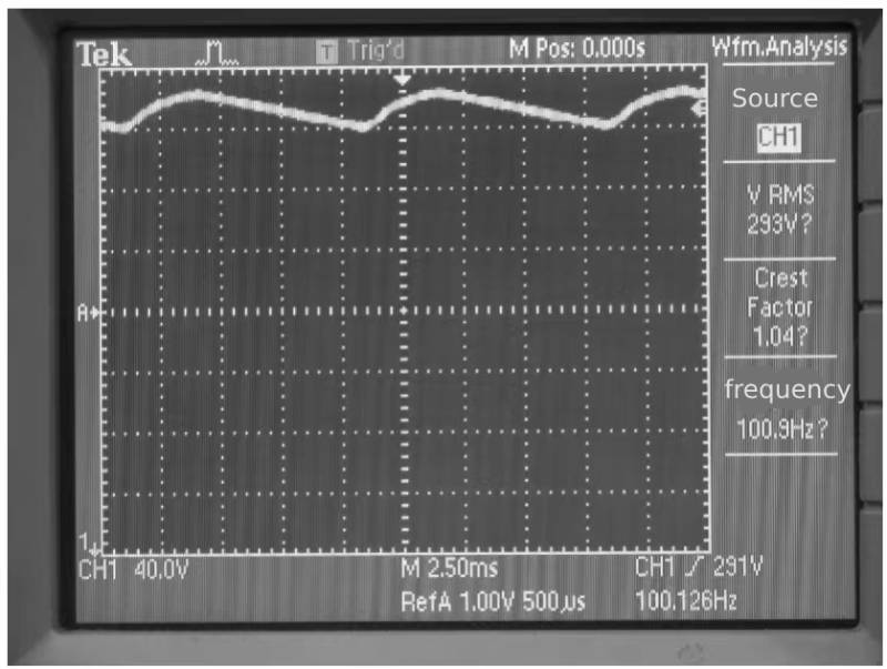
Figure 1-11 Rectifier filter circuit output voltage waveform
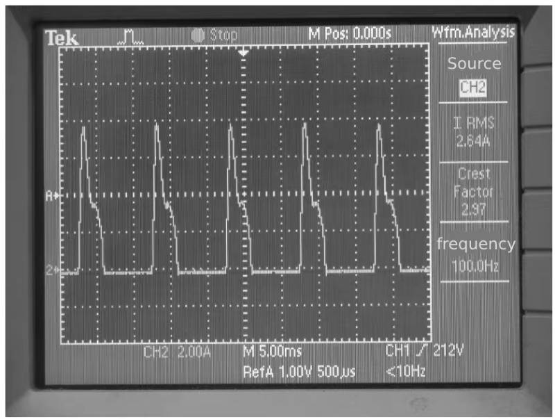
Figure 1-12 Rectifier output current of rectifier filter circuit
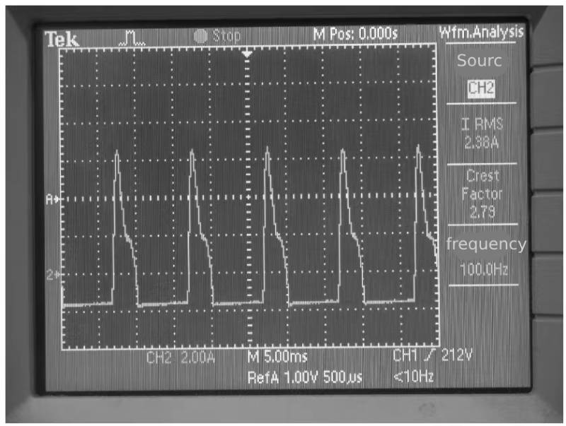
Figure 9-13 Ripple current of rectifier filter capacitor
Working status of electrolytic capacitors—the above is the analysis of the ripple current status of the input rectifier filter capacitor
2.4 Ripple current from flyback converter
The waveform of the current that the flyback converter obtains from the rectifier filter circuit and flows into the rectifier filter capacitor in the current intermittent state is shown in Figure 1-14.
In Figure 1-14, t1 is the conduction time of the switch tube, and T is the switching period of the switch tube. The current flowing into the rectifier filter capacitor is the effective value of the current required by the flyback converter from the rectifier filter circuit minus its DC component. You can first calculate the effective value of the current that the flyback converter requires from the rectifier and filter circuit, and then use the effective value principle to obtain the effective value of the current flowing into the rectifier and filter capacitor after deducting its DC component.
In order to obtain the average current required by the flyback converter from the rectifier filter circuit, it is
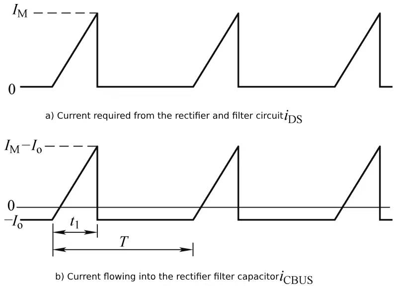
Figure 1-14 Main waveforms of flyback converter current discontinuity state

In the formula, IBUSav is the average value of the output current of the rectifier and filter circuit; Po is the output power of the buck converter; UBUS is the output voltage of the rectifier and filter circuit; eta is the efficiency of the flyback converter.
The relationship between the average output current of the rectifier filter circuit and the peak current is:

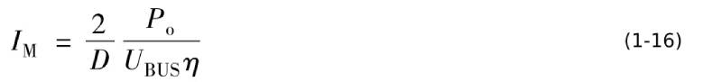
In the formula, IM is the current peak value of the flyback converter; D is the switching tube conduction duty cycle.
The relationship between the bus current peak value, output power and bus voltage is
The relationship between the current effective value IBUSrms requested by the flyback converter from the rectifier filter circuit and the current peak value is:
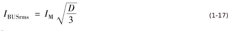
Substitute equation (1-16) into equation (1-17) to get

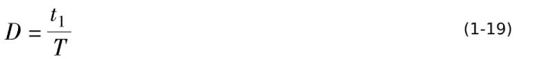
The relationship between t1 and T in Figure 1-14 is
According to the effective value principle, the current of the DC bus capacitor is

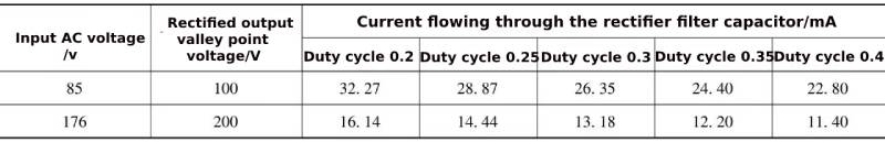
The corresponding effective values of the current flowing into the rectifier filter capacitor for different duty cycles and different AC input voltages under the condition of unit output power and efficiency of 80% are shown in Table 1-1.
Table 1-1 RMS current flowing into the rectifier filter capacitor
Working status of electrolytic capacitors – the above is the ripple current analysis from the flyback converter
2.5 The real choice of rectifier and filter capacitors
For capacitors that undertake rectification, filtering and bypass functions, a relatively large capacitance is required, so electrolytic capacitors become the only choice. In practical applications, the ability of electrolytic capacitors to carry current is low. If the capacitor is selected only based on the minimum capacitance of the rectifier filter capacitor, the capacitor will not be able to withstand the AC current component generated by the rectifier circuit and flyback converter.
According to the effective value formula, the actual current flowing through the rectifier filter capacitor is

In the formula, ICrms is the effective value of the ripple current flowing into the electrolytic capacitor; I100Hz is the 100Hz current component in the ripple current flowing into the electrolytic capacitor; ISW is the switching frequency current component in the ripple current flowing into the electrolytic capacitor. The ripple currents of the rectifier and filter capacitors of full-voltage switching power supplies and single-voltage switching power supplies are shown in Table 1-2.
Table 1-2 Rectifier and filter capacitor ripple current of full-voltage switching power supply and single-voltage switching power supply
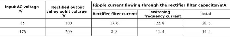
Under the AC input state of 85~265V international universal voltage level, the rectifier filter capacitor withstands an effective ripple current of approximately 29mA/W. At the lowest input voltage of 220V AC voltage level, the rectifier filter capacitor withstands an effective ripple current of approximately 15mA/W. Therefore, in most applications, electrolytic capacitors for filtering in switching power supplies need to be selected based on the current that the electrolytic capacitor can withstand.
For example, for a flyback switching power supply with an output power of 24W, if the input voltage is an international common voltage level of 85 to 265V, the rectifier filter capacitor will bear a current with an effective value of approximately 0.65A, and at least an electrolytic capacitor of 100μF/400V needs to be selected. Generally, a 100μF/400V electrolytic capacitor can withstand an effective current of 0.5~0.7A. This capacitor also exceeds the minimum capacitance of 72µF.
If the 24W flyback switching power supply is powered by 220V AC voltage level, the ripple current flowing through the rectifier filter capacitor is 0.32~0.33A, and the 33μF/400V electrolytic capacitor can withstand this effective value of current.
Since the ability of electrolytic capacitors to withstand ripple current does not increase linearly with capacitance, as the output power of the switching power supply increases, the required capacitance will be larger.
For example, for a flyback switching power supply with an output power of 100W, under the power supply condition of 85~265V international universal voltage level, the rectifier filter capacitor will withstand an effective current of 2.7A, and the electrolytic capacitor current withstanding capacity of 220μF/400V (CHEMI-CON The company’s SMQ series 85℃/2000h products) have a maximum current capacity of 1.4A. Even the current carrying capacity of the 470μF/400V electrolytic capacitor is only 2.39A, so a 560μF/400V electrolytic capacitor (2.69A) needs to be selected. If 220V power supply voltage level is selected, the capacitance can be reduced to 220μF/400V.
It can be seen that when it is not necessary (for example, it is only used domestically), the switching power supply does not need to be designed as a full-voltage type. Designing a single-voltage switching power supply can effectively reduce the cost of the switching power supply.
What will be the difference in the state of the electrolytic capacitor when the full-voltage switching power supply inputs 176V AC 220V × (1-20%) = 176V compared to the AC single-voltage switching power supply input 176V?
The switching tube conduction duty cycle of the full-voltage switching power supply at 85V is 0.4, and the peak switching tube current is 62.5mA/W. When the AC input voltage is 176V, the corresponding current peak value will also be 62.5mA/W. When the AC voltage is 176V, the corresponding switching tube conduction duty can be obtained according to Equation (1-16)

According to formula (1-18), the effective value of the current flowing through the rectifier filter capacitor is

Obviously, under the condition of DC bus voltage 200V, the effective value of unit power current obtained by the flyback converter from the DC bus is 14.4mA/W when using a single power supply switching power supply, and 16.14mA/W when using a full power supply switching power supply. Compared with the full power supply, the effective value of unit power current obtained by the flyback converter from the DC bus is reduced by 1.74mA/W, which is approximately 11%. This reduction is beneficial to the life of the electrolytic capacitor.
Working status of electrolytic capacitors – the above is the actual selection analysis of rectifier and filter capacitors
2.6 The problem of ripple current conversion coefficient of electrolytic capacitors
In Table 1-2, the root mean square formula is directly applied when calculating the current flowing through the rectifier and filter capacitor, without considering the ripple current conversion coefficient of the electrolytic capacitor. If the ripple current conversion coefficient is considered, the ripple current of the switching frequency is converted to the 120Hz frequency. above, the ripple current flowing through the corresponding electrolytic capacitor is equivalent to the ripple current at 120Hz. Electrolytic capacitors of different specifications have different frequency conversion coefficients, which are assumed to be 1.5 for the convenience of analysis. After frequency conversion, it is equivalent to the ripple current flowing through the electrolytic capacitor at a frequency of 120Hz, see Table 1-3.
Table 1-3 Equivalent ripple current of electrolytic capacitors for full-voltage switching power supplies and single-voltage switching power supplies
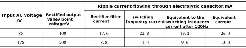
After frequency conversion, the equivalent ripple current flowing through the electrolytic capacitor in Table 1-3 is about 10% lower than the ripple current without frequency conversion given in Table 1-2. The reduction of this value has little impact on the selection and application life of electrolytic capacitors. Therefore, for the convenience of analysis, in the filtering scheme that uses capacitors directly after rectification, the square root of the 100Hz ripple current and the square root of the switching frequency ripple current can be directly applied. It is not necessary to convert the switch The frequency ripple current is converted and then calculated as root mean square.
However, if it is an electrolytic capacitor in a power factor correction circuit, its switching frequency ripple current component is significantly larger than the 100Hz ripple current component. At this time, considering the frequency conversion coefficient will have a significant impact on the final equivalent ripple current of 120Hz.
The frequency conversion coefficient of ripple current is the current ratio corresponding to the same temperature rise of the electrolytic capacitor core at different frequencies. It should be noted that only the same temperature rise is used as the basis for judgment. However, as the frequency of the ripple current increases, the distribution of the ripple current on the aluminum foil will change more and more obviously due to the influence of the parasitic inductance of the electrolytic capacitor. The current density of the aluminum foil near the guide pin or guide bar increases with the increase of the ripple current frequency, which may cause the filter near the guide pin or guide bar to overcurrent and cause early failure, which is manifested by the aluminum foil or oxide film being damaged. “Hydration” increases the ESR there. Of course, the above description is just speculation and needs experimental verification.
This early failure will gradually extend over time until the ESR index of the electrolytic capacitor reaches the failure criterion value. Therefore, if the existing frequency conversion coefficient of electrolytic capacitors is based on 100kHz, the frequency conversion coefficient of 120Hz is credible or may be low. If 120Hz is used as a reference, the conversion factor of 100kHz is questionable. It can be seen that the high-temperature load life test of electrolytic capacitors at 100kHz must be done.
Working status of electrolytic capacitors—the above is an analysis of the ripple current conversion coefficient of electrolytic capacitors
3 Working status of electrolytic capacitors in single voltage flyback switching power supply
Single voltage means that the switching power supply is only suitable for a single voltage level, such as single-phase 220V voltage level AC power supply. Under this power supply condition, the AC power supply voltage range can be 220V±20%, that is, 176~264V. Due to the improvement of the power supply quality of the State Grid, the power supply voltage can be 190~240V. This section takes 176~264V and 190~240V as examples for analysis.
In most cases, the input rectifier circuit for a single supply voltage is a single-phase bridge rectifier circuit, and electrolytic capacitors are used for filtering.
At this time, the maximum working voltage of the electrolytic capacitor may reach a peak effective value of 264V, about 370V. The voltage of the rectifier filter capacitor needs to be selected to be higher than and close to the nominal voltage of 370V, that is, the rated voltage is 400V. For high-voltage electrolytic capacitors, the actual operating voltage is 5% to 10% lower than the rated voltage, which can effectively extend the service life of the electrolytic capacitor.
If the AC input voltage is 190~240V, the rectified output voltage is about 339V. If the voltage range is below this voltage value, you can choose an electrolytic capacitor with a rated voltage of 350V or 400V.
The maximum rectified output voltage of a single-voltage switching power supply is the same as that of a full-voltage switching power supply, and the required rated voltage of the rectifier filter capacitor is also the same, that is, 400V.
The minimum rectified output voltage of a single-voltage switching power supply is twice that of a full-voltage switching power supply. Under the same output power condition, the rectified output current is halved, the ripple current flowing through the rectifier filter capacitor is also halved, and the capacitance of the electrolytic capacitor is also halved. Capacity is also at least halved.
Working status of electrolytic capacitors—The above is an analysis of the working status of electrolytic capacitors in single-voltage flyback switching power supplies.
4 The working status of the electrolytic capacitor – the working status of the output rectifier filter capacitor
In order to obtain the lowest possible output voltage spike, the operating mode of flyback switching power supply is mostly selected as current discontinuous mode, which allows the output rectifier to achieve reverse recovery in a zero current state, thus avoiding the conduction of the switch tube. The process occurs simultaneously with the reverse recovery of the output rectifier, resulting in a relatively strong parasitic oscillation.
In current discontinuous mode, the current waveforms of the output rectifier and output rectifier filter capacitor are shown in Figure 1-15.
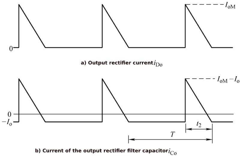
Figure 1-15 Current waveform of output rectifier and output rectifier filter capacitor
The relationship between the peak current IoM of the output rectifier and the average current Io is
 or
or
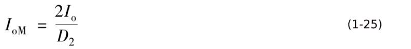
In the formula, D2 is the conduction duty cycle of the output rectifier.
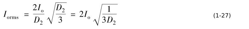
The relationship between the effective value of the output current of the output rectifier and the average value of the output current is:
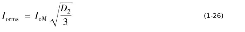
The corresponding relationship between the effective value of the output rectifier current and the average current value is:
After deducting the DC component, it is the effective value of the current flowing into the output rectifier filter capacitor, that is
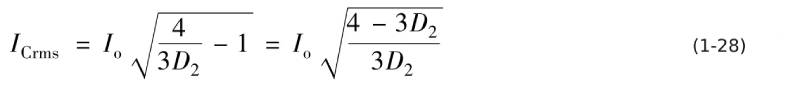
From Equation (1-28), it can be concluded that under the condition that the average value of the output current is the same, the relationship between the output rectifier conduction duty cycle and the effective current value is shown in Table 1-4.
Table 1-4 The relationship between output rectifier conduction duty cycle and current effective value

It can be seen from Table 1-4 that the larger the output rectifier conduction duty cycle, the smaller the effective current value. Considering only the output rectifier filter circuit, it is hoped that the larger the output rectifier conduction duty cycle, the better, which can reduce the current flowing through the output rectifier and reduce the heat of the rectifier, reduce the ripple current flowing into the output rectifier filter capacitor, and reduce the capacitor of fever.
The characteristic of the flyback converter is that in the critical current mode, the switching tube and the output rectifier are alternately turned on. The output rectifier has a large turn-on duty cycle, and the corresponding switch tube has a small turn-on duty cycle. Therefore, in theory, the optimal conduction duty cycle of the flyback converter is 0.5. Considering the compromise in the selection of switch tube withstand voltage, the switch tube conduction duty cycle is generally selected to be 0.35 to 0.4, and the corresponding output rectifier conduction duty cycle is 0.6 to 0.65. Generally, 0.6 is selected, and the corresponding current effective value is 1.106Io , it can be selected according to 110% to 120% of the average output current during quick design or selection.
Even so, the ripple current flowing through the output rectifier filter capacitor is very large. For example, the output of a mobile phone charger is 5V/2A, and the effective value of the ripple current flowing through the electrolytic capacitor reaches 2.2~2.4A. A high-frequency low-resistance electrolytic capacitor corresponding to a rated voltage of 10V that can withstand a ripple current of 2.4A requires 3300μF and a size of ϕ12.5×20mm. For mobile phone chargers with extremely strict size requirements, this size is never allowed. ! Therefore, solid electrolytic capacitors that can withstand large ripple currents (such as 680μF/10V solid electrolytic capacitors that can withstand about 5A ripple current and have a size of ϕ6.3×9mm) are irreplaceable in mobile phone chargers.
Working status of electrolytic capacitors -The above is an analysis of the working status of the output rectifier filter capacitor.
5 Working status of electrolytic capacitors – influence of ambient temperature and life requirements
For general-purpose electronic products, the application environment temperature is relatively low and will not exceed 45°C. Therefore, the maximum ambient temperature of general-purpose electrolytic capacitors is 85°C and the life span is 2000h. This temperature and life span are the lowest levels of electrolytic capacitors in my country today, and this type of electrolytic capacitor is also the cheapest.
According to the rule that the lifespan doubles for every 10°C decrease, the expected life of an 85°C/2000h electrolytic capacitor when working at an ambient temperature of 45°C is 16 times that of 2000h, that is, 32000h, which means that it can work continuously for about 4 hours at an ambient temperature of 45°C. years, it can meet the performance requirements of general-purpose electronic equipment. If you require longer life, you can choose electrolytic capacitors with a lifespan of 4000h or even longer.
If the operating temperature of electronic equipment is very high and the cost is not too high, you can choose electrolytic capacitors with a maximum ambient temperature of 105°C/2000h, or even electrolytic capacitors with a lifespan of 10000h.
Working status of electrolytic capacitors—the above is an analysis of the influence of ambient temperature and life requirements
Summarize:
Working status of electrolytic capacitors -This article mainly talks about the working status of electrolytic capacitors in full voltage, single voltage and flyback switching power supplies.If you want to know more about capacitors, please click:https://xuansncapacitor.com