1 How electrolytic capacitors work—Inverter arc welding power supply working mode
How electrolytic capacitors work—Inverter arc welding power supply is a special working mode of high-power switching power supply. Its particularity is not only that the working characteristics of arc welding require constant current, but more importantly, in order to facilitate arc starting, it generally requires 2 times the welding voltage or even higher arc starting voltage.
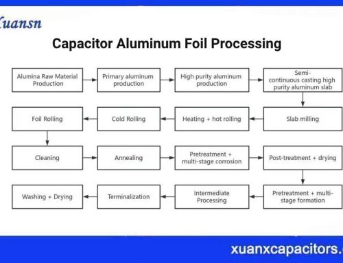
The arc voltage of arc welding is about 20~30V, and the corresponding arc starting voltage is about 60~70V. The volt-ampere characteristics required for arc welding are shown in Figure 1-1.
In Figure 1-1, low voltage has an external drag characteristic, that is, the current increases slightly at low voltage. The voltage of the arc welding power source does not need to be precisely controlled to keep the voltage constant, and is allowed to vary slightly, so it can be called a voltage limiting/constant current characteristic.
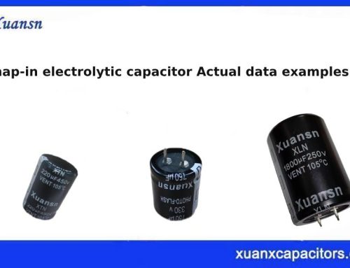
The first one to obtain similar characteristics as shown in Figure 1-1 was the arc welding transformer. The volt-ampere characteristics output by the arc welding transformer are shown in Figure 1-2. This is a high leakage reactance transformer that obtains constant current characteristics through high leakage reactance and changes the output characteristics by adjusting the magnetic shunt to adjust the welding current.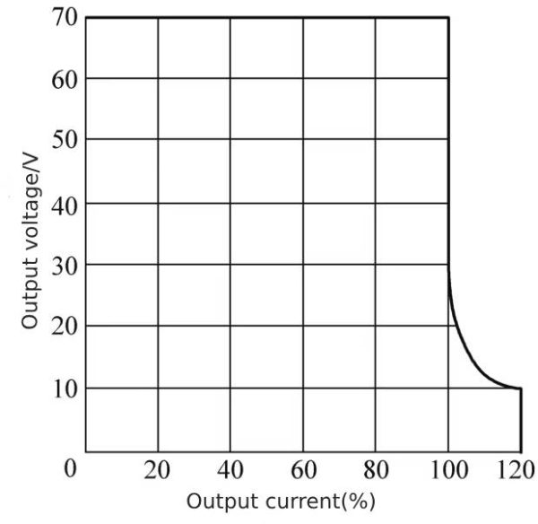 Figure 1-1 Voltage-ampere characteristics required for arc welding
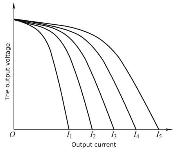 Figure 1-2 Volt-ampere characteristics of arc welding transformer output
The main disadvantages of the welding transformer are: the welding transformer is a single-phase transformer, which is a large load, which will cause a serious imbalance in the load of the three-phase power supply; the power factor of the welding transformer is very low; the welding characteristics are functional, but not ideal.
In order to solve the unbalanced three-phase power supply and improve the welding characteristics, a welding generator appeared, which uses a three-phase asynchronous motor to drive a DC generator with welding characteristics.
But both welding transformers and welding generators are inefficient solutions. With the development of power electronics technology, welding power supplies have entered the era of switching power supplies.
A switching power supply is an electric energy conversion device that integrates power electronics technology and automatic control theory. It can not only realize a switching-type regulated power supply with a constant voltage function, but also a current source with a constant current function. Of course, it can also realize a constant voltage function. , constant voltage and constant current power supply with current limiting function, the most classic one is the charger.
The voltage limiting and constant current characteristics are exactly what welding power sources require, but the power is slightly larger. However, the on-board charger for electric vehicles has entered the 10kW power level, and the inverter arc welding power supply with an output current of 300A is only 10kW.
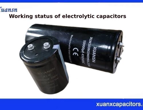
The output characteristics of the inverter arc welding power supply are shown in Figure 1-3.
The inverter arc welding power supply uses a full-bridge converter. When the output is in no-load or constant voltage state, the duty cycle of the full-bridge converter can reach 0.95, which is close to 1.
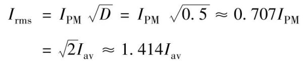
In the welding state, the working voltage is about 1/2 of the constant voltage mode, and the duty cycle of the inverter drops from 1 in the constant voltage mode to 0.5 or 0.4. In this state, the current the full-bridge converter draws from the DC bus is a rectangular wave current with a duty cycle of 0.5. In this state, the relationship between the effective value of the DC bus current and the average value is
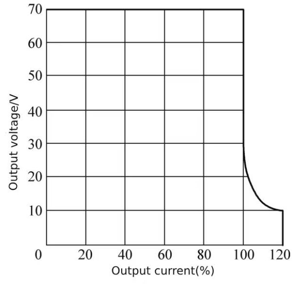 Figure 1-3 Inverter arc welding power supply output characteristics
2 How electrolytic capacitors work—Working mode of electrolytic capacitor in simple single-phase narrow voltage AC input inverter arc welding power supply
This section covers inverter arc welding power supplies with narrow voltage range input, that is, single power supply voltage level AC input. The most common one is the inverter arc welding power supply with 220V voltage level input. The focus is on the current flowing through the DC bus capacitor.
From formula (10-7), the relationship between the current flowing through the DC bus capacitor and the average value of the DC bus current is:
The inverter arc welding power supply requires low voltage, and the output also needs to be isolated from the AC power grid. Therefore, the inverter arc welding power supply requires a transformer for voltage conversion and isolation. It can usually be considered that the DC bus voltage is about 300V, the output constant voltage is 60V, the corresponding transformer voltage ratio is 5, and the corresponding ratio of the output current to the DC bus current peak is 1:5. If the inverter arc welding power supply outputs 300A, the corresponding current The ratio is 5:1, corresponding to a DC bus current peak value of 60A, an average value of approximately 43A, and a DC bus capacitor current of 40~50A.
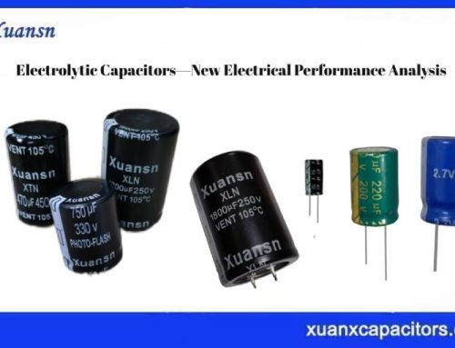
Figure 1-4 shows the 225A inverter arc welding power supply.
The maximum output current of the 225A inverter arc welding power supply is 225A. When the transformer voltage ratio is 5:1, the corresponding DC bus current peak value is 45A, and the effective value of the current flowing through the DC bus capacitor is 22.5A. This is only the ripple current drawn by the bridge inverter, the rectifier will also generate ripple current. The corresponding output power in the 225A output current mode is about 6.5kW, and the corresponding ripple current flowing through the DC bus capacitor is 65A. The total ripple current combined with the ripple current of the full-bridge inverter is
It can be seen from this result that the main part of the current flowing through the DC bus capacitor in the 220V direct rectification/capacitor filter mode is the current generated by the rectifier filter circuit. Corresponding to two 680μF/400V electrolytic capacitors connected in parallel, the current flowing through each electrolytic capacitor is 34.5A.
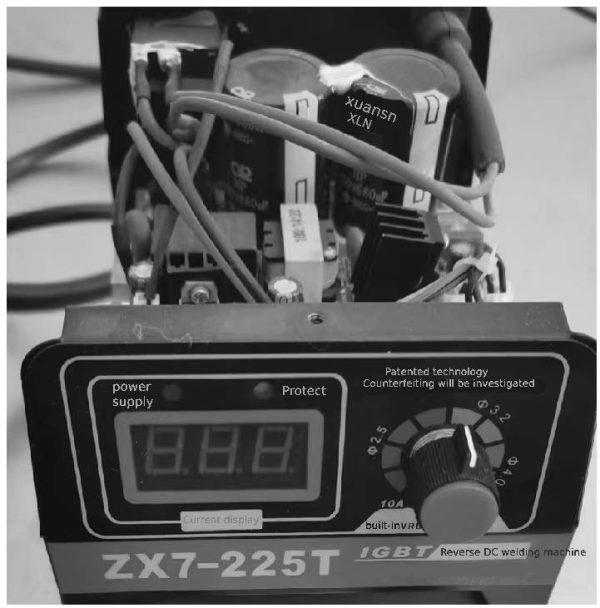 Figure 1-4 225A inverter arc welding power supply
The ripple current that can flow through a 680μF/400V electrolytic capacitor is 2.6A (120Hz), and 34.5A corresponds to an overload of 1300%, which is far beyond the safe working area of the electrolytic capacitor. The results of the application can only be suitable for short-time work, which is exactly the working condition of manual welding. Even so, the life of the electrolytic capacitor in the inverter arc welding power supply is very short, less than 500h, or even less than 200h.
How electrolytic capacitors work—The above is an analysis of the working mode of electrolytic capacitors in a simple single-phase narrow voltage AC input inverter arc welding power supply.
3 How electrolytic capacitors work—Working mode of electrolytic capacitor in simple single-phase AC ultra-wide voltage input inverter arc welding power supply
In order to adapt to more application scenarios, some inverter arc welding power sources need to have an ultra-wide input voltage range, that is, 220V and single-phase 380V voltages are compatible. Not only that, but also need to consider the poor power supply environment, such as the input voltage drop of the 220V voltage level. to below 150V, even 130V. Therefore, when designing an inverter arc welding power supply, it is necessary to consider the operating voltage and current that can normally meet the requirements of the arc welding process within an ultra-wide voltage range.
Figure 1-5 shows a certain inverter arc welding power supply with 315A output and ultra-wide voltage range input.
As can be seen from Figure 1-5, the input voltage range is 130~520V single-phase AC, and the output current is 315A. Choose 6 560μF/400V electrolytic capacitors. Considering that the maximum input voltage is 520V, the six electrolytic capacitors should be connected in a “two series and three parallel” connection method, as shown in Figure 1-6 and Figure 1-7.
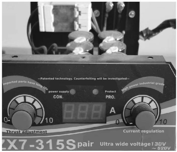 Figure 1-5 Wide voltage 315A inverter arc welding power supply
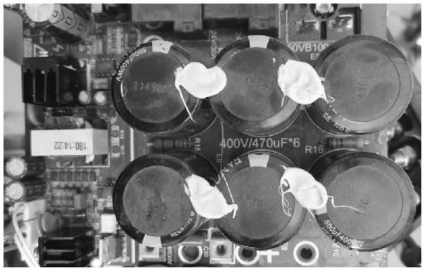 Figure 1-6 Front of circuit board of wide voltage 315A inverter arc welding power supply
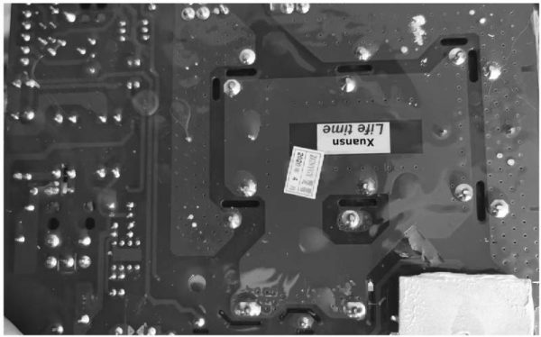 Figure 1-7 The reverse side of the wide voltage 315A inverter arc welding power supply circuit board
As can be seen from the circuit board layout in Figure 1-7, the six electrolytic capacitors are in two series and three parallel, and the DC bus voltage is 500~550V. The working mode of the rectifier circuit is single-phase voltage doubler/bridge rectification. The wiring method can be separate wiring for 220V and 380V, as shown in Figure 1-8, and the common terminal connection method for 220V and 380V is shown in Figure 1-9.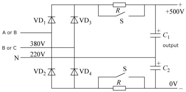 Figure 1-8 Input connection method of inverter arc welding power supply connected to 220V and 380V respectively
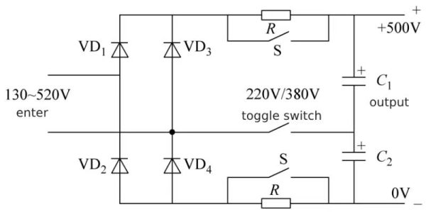 Figure 1-9 Input connection method of inverter arc welding power supply connected to the common terminal of 220V and 380V
The working modes of electrolytic capacitors C1 and C2 in Figure 1-8 and Figure 1-9 are the same. The working modes of the electrolytic capacitors in the figure can be divided into voltage doubler rectification and bridge rectification modes. It works in the voltage doubler rectification mode when the voltage level is 220V, and the bridge rectification mode when the voltage level is 380V.
In low-voltage input mode, both the rectifier and the electrolytic capacitor will bear the maximum current stress, so only the electrolytic capacitor current stress at the lowest input voltage needs to be analyzed.
An inverter arc welding power supply with an output current of 315A will output about 10kW of power, corresponding to a voltage doubler rectifier no-load output voltage of about 370V, and the corresponding transformer voltage ratio can be 6:1. The peak current drawn from the DC bus by the full-bridge inverter used is 52.5A, and the corresponding ripple current flowing into the electrolytic capacitor is
When the input is 130V in voltage doubler rectification mode, the corresponding effective input current value can be referred to the full-bridge rectifier circuit.
At an input voltage of 220V-20%=170V, for every 1W of power input, a ripple current of approximately 10mA will flow into the filter capacitor; corresponding to an input voltage of 130V, for every 1W of power input, a ripple current of approximately 13mA will flow into the filter capacitor. In a voltage doubler rectifier circuit with the same input current, each capacitor will bear a ripple current of 9.2mA/W. Corresponding to 10kW power, in the circuit shown in Figure 13-8, each capacitor will bear a ripple current of 92A (50Hz). According to the general electrolytic capacitor CD293 data, 92A/50Hz is converted to 115A at 120Hz.
For the rectifier filter capacitor, the 115A ripple current generated by the voltage doubler rectifier and the 37.12A ripple current generated by the full-bridge inverter need to work together, and the effective value is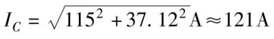
This 121A ripple current will be “equally shared” among three parallel-connected 560μF/400V electrolytic capacitors, each flowing through a 40.3A ripple current. The 560μF/400V universal electrolytic capacitor CD293 can only withstand 2.3A/120Hz ripple current, and 40.3A will be overloaded by 1752%! (17 times)
If the power supply conditions are relatively good and can work at 220V, the electrolytic capacitor ripple current will still be overloaded by 1035% or 10.35 times.
Working under 380V conditions, according to the conversion relationship between the ripple current of the single-phase bridge rectifier circuit and the output power, the rectifier filter capacitor will withstand a ripple current of 3.4mA/W, corresponding to 10kW power, and the 120Hz ripple flowing into the rectifier filter capacitor The effective current value is 34A.
The rectified output voltage corresponding to the 380V input voltage is about 530V. When the rectified output voltage is 340V, the inverter operating duty cycle of the full-bridge inverter is 0.5, and the corresponding inverter operating duty cycle at the rectified output voltage of 530V is 0.32.
![]() The total ripple current under the action of two ripple currents is
The total ripple current under the action of two ripple currents is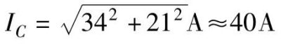
For the three-parallel method, each electrolytic capacitor flows through a ripple current of 13.3A, which corresponds to the 2.3A ripple current endurance of the general-purpose electrolytic capacitor CD293 with a specification of 560μF/400V, and the overload is 580% or 5.8 times. This value is about 1/2 of the 220V input.
To sum up, for the 300A output level, single-phase AC power supply is usually not suitable, and it is more suitable for three-phase AC power supply, especially for continuous operation of inverter arc welding power supply.
How electrolytic capacitors work—The above is an analysis of the working mode of electrolytic capacitors in a simple single-phase AC ultra-wide voltage input inverter arc welding power supply.
4 How electrolytic capacitors work— Analysis of DC bus voltage drop of simple inverter arc welding power supply
During the operation of the single-phase bridge rectifier and capacitor filter circuit, only when the instantaneous value of the AC input voltage is higher than the terminal voltage of the filter capacitor, the diode in the rectifier bridge can be turned on, and the AC power supply can provide power to the output of the rectifier and the filter capacitor through the rectifier. , the rest of the time, the electric energy at the output end of the rectifier is provided by the filter capacitor in the form of releasing energy storage, which will cause the voltage at the filter capacitor end to drop.
The voltage drop can be divided into two parts: the voltage drop during the switching cycle and the voltage drop during the power frequency cycle.
4.1 How electrolytic capacitors work—Voltage drop during switching cycle
The voltage drop during the switching cycle is the process in which the filter capacitor supplies power to the full-bridge inverter in the form of discharge during the conduction period of the switch tube in the full-bridge inverter.
First, look at the simple inverter arc welding power supply with a single power supply voltage output of 225A current.
Assume that the transformer voltage ratio is 5:1, the switching frequency is 20kHz, the inverter operating duty cycle is 0.5, the switching tube conduction time is 25μs, two 680μF electrolytic capacitors are connected in parallel (equivalent capacitance is 1360μF), and the output current is At 225A, the corresponding full-bridge inverter draws a peak current of 45A from the filter capacitor.
During the conduction period of the switch tube, the amount of charge required by the full-bridge inverter from the filter capacitor is
Q=It=45×25×10m-6C=1125×10m-6C=1125μC
Through the relationship between charge, capacitance and capacitor terminal voltage, we can get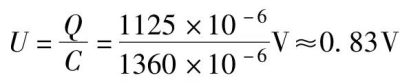
Let’s look at the ultra-wide voltage range 315A single power supply voltage simple inverter arc welding power supply.
Assume that the transformer voltage ratio is 6:1, the switching frequency is 20kHz, the inverter operating duty cycle is 0.5, the switching tube conduction time is 25μs, and two groups of three 560μF electrolytic capacitors are connected in parallel and then in series (equivalent capacitance is 840μF), When the output current is 315A, the corresponding full-bridge inverter draws a peak current of 52.5A from the filter capacitor.
During the conduction period of the switch tube, the amount of charge required by the full-bridge inverter from the filter capacitor is
Q=It=52.5×25×10-6C=1312.5×10-6C=1312.5μC
Through the relationship between charge, capacitance and capacitor terminal voltage, we can get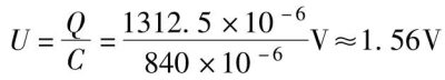
For a 530V DC bus voltage, the voltage drop of 1.56V is very small and can be ignored. Even if the capacitance is small, it will not affect the working status of the inverter.
4.2 Voltage drop during power frequency cycle
The time for the half-wave rectifier to provide power to the filter capacitor and the output of the rectifier at each power frequency (50Hz) is about 2ms. The remaining 8ms need to be supplied to the output through the discharge of the filter capacitor, resulting in the filter capacitor terminal voltage (DC bus voltage) of falling. In a simple inverter arc welding power supply, how big will the voltage drop be?
First, analyze the simple inverter arc welding power supply with single power supply voltage level and 225A output. The output power is about 6kW when outputting 225A current. The peak current reflected from the 225A output current to the input end of the full-bridge inverter is 45A. Assuming that the duty cycle of the full-bridge inverter is 0.5, the average current drawn by the full-bridge inverter from the DC bus is 22.5A.
The filter capacitor releases energy storage time to the output is 8ms, and the corresponding charge amount is
Q=It=22.5×8×10m-3C=0.18C
Corresponding to 1360μF capacitance, the voltage change generated by the charge is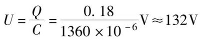
For the inverter arc welding power supply with ultra-wide input voltage and 315A output, there are two modes: voltage doubler rectification and bridge rectification.
In the voltage doubler rectification mode, during the entire power frequency cycle, the rectifier charges the filter capacitor once, and the charging time is about 2ms. The remaining 18ms is when the filter capacitor releases stored energy to the rectifier output in the form of discharge.
The equivalent capacitance of the filter capacitors C1 and C2 in this inverter arc welding power supply is 1680μF (three 560μF capacitors are connected in parallel). The output power is about 10kW when outputting 315A current. The peak current reflected from the 315A output current to the input end of the full-bridge inverter is 52.5A. Assuming that the duty cycle of the full-bridge inverter is 0.5, the average current drawn by the full-bridge inverter from the DC bus is 26.25A.
The filter capacitor releases energy storage time to the output is 18ms, and the corresponding charge amount is
Q=It=26.25×18×10m-3C=472.5×10m-3C
Corresponding to 1680μF capacitance, the voltage change generated by the amount of charge is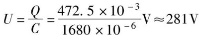
In the bridge rectification mode, the equivalent capacitance of the filter capacitor is 840μF, the filter capacitor releases energy storage time to the output is 8ms, and the corresponding charge amount is
Q=It=26.25×8×10m-3C=210×10m-3C
Corresponding to 840μF capacitance, the voltage change generated by the amount of charge is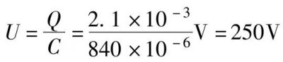
5 How electrolytic capacitors work—Working mode of electrolytic capacitor in inverter arc welding power supply with three-phase AC input
For high-quality inverter arc welding power sources, the mode selected for the capacitor in Section 3 is not suitable. The main reasons are: high-power single-phase power supply has a greater impact on the power supply quality of the grid; the capacitor works in extreme overcurrent mode and has a very short life. Short-term working mode suitable for manual welding. For continuous welding, the selection of filter capacitors in Sections 2 and 3 is intolerable, and single-phase AC power supply is undesirable. It is advisable to use three-phase AC power supply, which not only solves the problem of three-phase unbalanced power supply caused by single-phase high-power power supply, but also solves the serious overcurrent application problem of “filter” capacitors.
5.1How electrolytic capacitors work— Three-phase rectifier circuit does not require “filter” capacitors
Among the three-phase rectifier circuits, the most cost-effective rectifier circuit is the three-phase bridge rectifier circuit, as shown in Figure 1-10.
Since the three-phase bridge rectifier circuit only requires three-phase power and three phase lines, it can be directly connected to the three-phase AC power grid without the need for a rectifier transformer and neutral wire. The circuit is the simplest.
The output voltage waveform of the three-phase bridge rectifier circuit without filtering is shown in Figure 1-11.
It can be seen from Figure 1-11 that under the condition of no filter circuit, the average output voltage of the three-phase bridge rectifier circuit is 1.35 times the effective value of the AC line voltage, the voltage peak is 1.0477 of the average rectified output voltage, and the output voltage valley The point voltage value is 91% of the average value of the output voltage. That is to say, even without filtering, the output voltage fluctuation of the three-phase bridge rectifier circuit is an average upward fluctuation of 4.77% and a downward fluctuation of 9%. Therefore, even if there is no filter component for filtering, the three-phase rectified output voltage will be relatively smooth, so in theory, smoothing filtering can even be unnecessary in many applications.
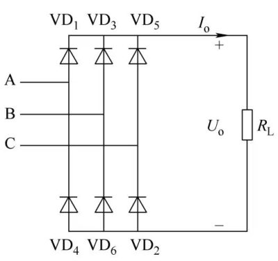 Figure 1-10 Three-phase bridge rectifier circuit
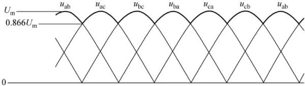 Figure 1-11 Output voltage waveform of three-phase format rectifier circuit
Obviously, the voltage fluctuation output by the three-phase bridge rectifier circuit can fully satisfy the inverter arc welding power supply, and “filter” capacitors are not necessarily needed.
5.2 The role of the capacitor at the output end of the rectifier of the inverter arc welding power supply of the three-phase rectifier circuit
Rectifier circuits are the power supply method used in most fixed electrical and electronic equipment. Compared with battery power supply, rectifier circuits can use relatively cheap AC mains power and can obtain very high output power. Since there is a certain parasitic inductance in the AC power grid, this parasitic inductance will be reflected in the equivalent circuit of the rectifier circuit and become the equivalent series inductance of the DC circuit.
The parasitic inductance of the AC power grid is equivalent to the equivalent series inductance of the DC output end. For a three-phase 380V voltage system, the parasitic inductance is at least 100 μH.
If the sine wave current acts on the parasitic inductance of the power supply, it can be known according to the circuit principle
![]()
Then the inductive reactance of 100μH parasitic inductance under power frequency AC power is only 31.4mΩ. Even if a current of 100A flows, the voltage drop generated is only 3.14V, which is less than 1% of 380V. In a 380V AC power grid, this voltage drop It should not affect the normal operation of the load.
However, this inductance is reflected on the output side of the rectifier, and when the rectifier outputs high-frequency AC current, a relatively large voltage drop will occur. For example, an AC load current component of 3kHz and 10A will produce a voltage change of 18.8V on a 100μH inductor, and the corresponding peak-to-peak value is 53.16V; if it is an AC load current component of 50kHz, a voltage change of 313V will be produced, corresponding to Peak-to-peak is 882.66V. It is obvious that under high frequency conditions, even a small parasitic inductance will affect the circuit state.
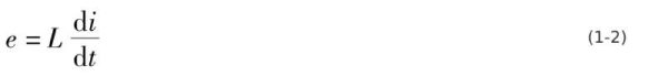
When the current changes rapidly, it is necessary to follow the law of electromagnetic induction, that is,
In power electronic circuits, the current change rate during the switching process can reach 100~1000A/μs. Even if the current change rate is 100A/μs, the transient voltage generated on this inductor can reach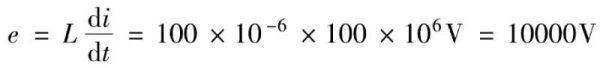
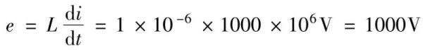
Or the current change rate of 1000A/μs acts on the 1μH parasitic inductance
Both of these results are not allowed in power electronic circuits. Therefore, it is necessary to suppress the impact of high-frequency alternating current or current change rate on the DC bus voltage, and reduce the high-frequency alternating current or current change rate to produce excessive high-frequency AC voltage or DC transient voltage.
5.3 Effect of capacitors connected in parallel with DC power supply
The simplest way to suppress or eliminate the influence of AC current on the voltage at the output end of a DC power supply or the voltage at the load end is to connect a suitable capacitor in parallel with the output end of the DC power supply or the load end.
The equivalent circuit of a DC power supply connected in parallel with a capacitor at the output end is shown in Figure 1-12.
In Figure 1-12, the capacitor should be as close to the load end as possible to minimize the impact of the load AC current on the DC power supply voltage.
For the convenience of analysis, it is assumed here that there is no AC current component on the DC power supply side, and the AC current component in the circuit comes from the load.
The corresponding AC equivalent circuit is shown in Figure 1-13.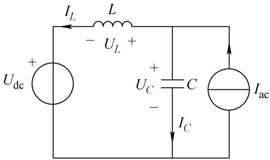 Figure 1-12 Equivalent circuit of a DC power supply with a capacitor connected in parallel at the output end
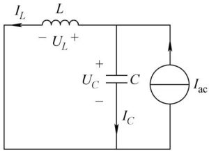 Figure 1-13 AC equivalent circuit
The current in the parasitic inductance of the DC power supply is
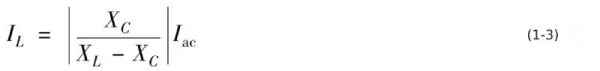 The corresponding current on the capacitor is
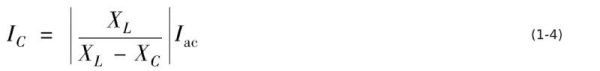
It can be seen from equations (1-3) and (1-4) that if the capacitive reactance of the capacitor and the inductive reactance of the parasitic inductance of the DC power supply are numerically equal, the equivalent circuit in Figure 1-13 will enter the parallel resonance state. , extremely high currents and AC voltages will be generated on capacitors and inductors. Such a result runs counter to the application of capacitors to offset the adverse effects of the parasitic inductance of the DC power supply under the action of the AC load current. Therefore, it is important to avoid this situation from happening.
In order to reduce the voltage of the AC current of the load on the parasitic inductance of the DC power supply, it is necessary to reduce the AC current component on the inductor. This requires the capacitor connected in parallel at the output end of the DC power supply to shunt the AC current of the load as much as possible, and the capacitor needs to have as low a capacitive reactance as possible.
The capacitor at the output end of the DC power supply also has different functions in different circuits, load conditions, and DC power supplies.
5.4 Minimum capacitance required for the DC bus of the inverter arc welding power supply of the three-phase bridge rectifier circuit
Taking the output of 315A inverter arc welding power supply as an example, the average output voltage of the three-phase 380V bridge rectifier is about 530V, the no-load voltage can exceed 560V, and the corresponding transformer voltage ratio can be 7:1, then the peak current reflected to the DC bus is 45A, and the average current is 22.5A. From formula (10-7), the AC current component flowing into the DC bus capacitor is
When the switching frequency is 20kHz and the inverter operating duty cycle is 0.5, the amount of charge a current pulse inverter requires from the DC bus is
Q=It=22.5×25×10m-6C=562.5×10m-6C=562.5μC
After deducting half of the DC component charge, the pulse charge is 281.25μC, corresponding to a capacitance of 4.7μF. The peak-peak value of the DC bus voltage fluctuation is 60V, which is approximately 11% of the DC bus voltage. If this voltage fluctuation is allowed, the output end of the three-phase bridge rectifier circuit can only be connected in parallel with a capacitor of 4.7μF, which is equivalent to a power of 2217W per unit capacitance. This can be ignored for a capacitance of 1000μF.
The relevant waveform of the rectifier filter circuit with a power of 700W/μF is shown in Figure 1-14.
Figure 1-14 AC input current waveform of the three-phase rectifier circuit when the filter capacitor power is 700W/μF
The corresponding input voltage and input current waveforms are shown in Figure 1-15.
Figure 1-15 Input voltage and input current waveforms of the three-phase rectifier circuit when the filter capacitor power is 700W/μF
The output current waveform of the rectifier circuit is shown in Figure 1-16.
In Figure 1-16, the effective value of the output current of the rectifier circuit is 1.90A.
Obviously, the output current waveform of the rectifier circuit is different from the output voltage waveform, and the current waveform provided by the rectifier circuit to the resistive load will be the same as the output voltage waveform, as shown in Figure 1-17. Figure 1-16 Output current waveform of rectifier circuit
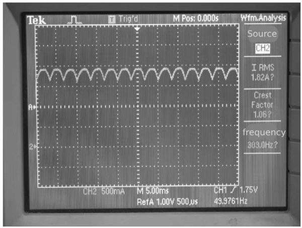
Figure 1-17 Current waveform provided by the rectifier circuit to the resistive load
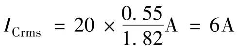
The effective value of the current in Figure 1-17 is 1.82A.
The effective value of the current flowing into the capacitor is
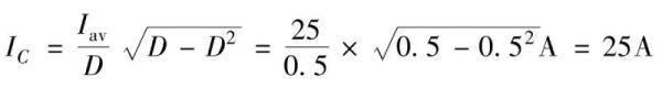
The output power of the 300A inverter arc welding power supply in the welding state is 10kW. The bus voltage corresponding to the DC of the three-phase 380V bridge rectifier circuit is about 550V, and the average current is about 20A. The effective value of the ripple current generated by the three-phase bridge rectifier circuit is
This current is much smaller than the ripple current value of nearly 40A under large capacitance filtering.
The ripple current generated on the inverter side: the transformer voltage ratio is 8:1, and the peak current on the primary side is about 50A. According to formula (10-8), when the inverter operating duty cycle is 0.5, the corresponding average current is 25A. It can be obtained that the effective value of the current input by the inverter to the DC bus capacitor is
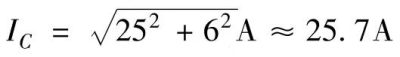
 The total current flowing into the DC bus capacitor is
If the DC bus capacitor specification is 1000W/μF and the capacitance of the filter capacitor is 10μF, an appropriate film capacitor can withstand a ripple current of 25A. Therefore, in theory, it is not necessary to select large-capacity filter capacitors for inverter arc welding power supplies with three-phase AC input, but only capacitors that can absorb the ripple current of the inverter switching frequency.
According to this idea, some three-phase 380V input inverter arc welding power supplies directly connect bus buffer capacitors with relatively large capacitance in parallel to the DC power supply end of the insulated gate bipolar transistor. A possible disadvantage of this capacitor selection is that electromagnetic interference can enter the AC grid. If electromagnetic compatibility requirements need to be met, it will be inappropriate to use a small capacitance filter capacitor method.
How electrolytic capacitors work—The above is an analysis of the working mode of electrolytic capacitors in inverter arc welding power supplies with three-phase AC input.
6 How electrolytic capacitors work—Inverter resistance welding power supply working mode
Resistance welding uses high current to fuse the resistance welded parts of the metal parts to be welded together.
The earliest resistance welding power supply used a resistance welding transformer to convert single-phase alternating current into low voltage and high current. However, resistance welding requires high power. Single-phase high-power power supply is not conducive to three-phase balance. At the same time, the resistance welding transformer also has the problem of low power factor. Since the welding current is very large, at least 1000A or more, the commutator of the welding DC generator will bear such a large current, which will cause the commutator to be expensive and no longer suitable for resistance welding DC generators. If you choose a rectifier, it would be superfluous to also use a power frequency transformer.
When welding robots are widely used, power frequency resistance welding transformers are no longer suitable. Thanks to the engineering of modern power electronics technology and the industrial application of insulated gate bipolar transistors as well as the maturity of circuit topology and manufacturing technology of high-power switching power supply technology, it has become inevitable to apply switching power supply technology to resistance welding, that is, the emergence of inverter resistance welding power supply .
The main circuit diagram of the inverter resistance welding power supply is shown in Figure 1-18.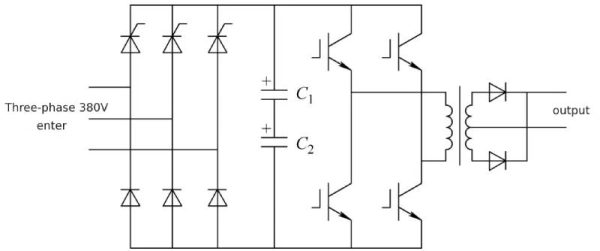 Figure 1-18 Main circuit diagram of inverter resistance welding power supply
In 1-18, C1 and C2 are electrolytic capacitors. C1 and C2 can use multiple electrolytic capacitors in parallel to solve the capacitance and ripple current requirements.
The output current of the inverter resistance welding power source ranges from 1000A to 20kA, and can even reach 1MA when multiple machines are connected in parallel! The maximum output voltage is about 10~14V. Compared with the actual working voltage, this output voltage leaves nearly half a voltage margin to ensure the welding set current.
The load state of resistance welding depends on the resistance of the welding clamp and the resistance of the object being welded. Under most working conditions, the output voltage of the inverter resistance welding power supply is mostly about 1/2 of the maximum output voltage. The switching tube in the corresponding inverter resistance welding power supply will work at 50% duty cycle, and the DC bus capacitor will withstand the maximum effective current value.
The working modes of resistance welding can be divided into spot welding and continuous welding. Spot welding is when two electrode contacts are pressed against the workpiece to be welded and then a welding current is applied. After the welding is completed, the next welding spot is welded. The spot welding working mode is: clamp the welding clamp, weld, loosen the welding clamp, move the welding clamp to a new position, clamp the welding clamp again, and weld.
It can be seen from this that the inverter resistance welding power supply only works during the welding stage during the entire process, and the power supply does not work. Therefore, the duty cycle of the inverter resistance welding power supply is low, generally 0.2 to 0.4.
Continuous welding is a form of seam welding.
Today’s resistance welding power sources need to deliver precise welding energy and voltage. Therefore, the DC bus of the inverter resistance welding power supply needs a relatively stable voltage. It cannot have the 150V or higher voltage fluctuation of energy-saving lamps, nor can it have the 100-200V voltage fluctuation of the DC bus of the simple inverter arc welding power supply.
How electrolytic capacitors work—The above is the analysis of the working mode of inverter resistance welding power supply.
7 How electrolytic capacitors work—The minimum capacitance required for the DC bus of the inverter resistance welding power supply
7.1 How electrolytic capacitors work—Minimum capacitance required for the switching process of the full-bridge inverter
The minimum capacitance required for an inverter resistance welding power source is the capacitance required to limit the DC bus voltage drop during switching of the switch tube within the allowable range. This minimum capacitance is related to the switching frequency and operating current of the inverter resistance welding power source. The lower the switching frequency, the more electric energy the DC bus capacitor needs to release, and the greater the magnitude of the voltage drop; the greater the operating current, the greater the magnitude of the voltage drop at the same switching frequency.
The switching frequency of the inverter resistance welding power supply is restricted by the frequency characteristics of the magnetic material of the transformer and the characteristics of the output rectifier diode. From the case of the inverter arc welding power supply, the magnetic material can work at 20kHz, so the switching frequency is no longer restricted by the magnetism of the transformer. Material.
Looking at the output rectifier, the output rectifier not only needs a very large forward current tolerance, but also has good reverse recovery characteristics. For a diode, the greater the output current, the worse its reverse recovery characteristics. Not only that, the reverse recovery characteristics under sine wave voltage conditions are much better than those under rectangular wave voltage conditions.
Most inverter resistance welding power sources use rectangular wave voltage output post-rectification mode, so the reverse recovery requirements of the output rectifier are very high. Therefore, even when the output current of the inverter resistance welding power supply is 1000A, the switching frequency will not reach the switching frequency of the inverter arc welding power supply. For an output current of 1000~3000A, when the switching frequency is about 10kHz, the maximum conduction time of the switch tube is 50μs, and it is 25μs when the duty cycle is 0.5.
Taking the output current as 1000A as an example, the output voltage of the rectifier on the input side is 300V (220V voltage level input), the output no-load voltage is 10V, and the power supply power is 10kW. When applying a full-bridge inverter circuit, the corresponding transformer voltage ratio can be 30:1, then the peak load current reflected to the DC bus is 33A, and the average DC value is 16.5A when the duty cycle is 0.5. The corresponding AC current component flowing through the rectifier filter capacitor can be obtained through equation (10-8), which is 16.5A.
The amount of charge during the conduction period of the switch is
Q=Iton=16.5×25×10m-6C=412.5×10m-6C
If the DC bus voltage fluctuates 60V, the capacitance only needs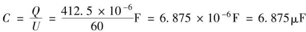
Obviously this is a very small capacitance.
7.2Minimum capacitance required for half cycle of power frequency
Since the single-phase bridge rectifier needs to smooth the rectified output voltage, the capacitance of the capacitor is required to be large. However, the capacitance is provided according to 5W/μF at full load. 10kW requires a capacitance of 2000μF. Such a capacitance will increase during half a cycle of the power frequency. How much voltage drop will occur at half load?
For a single-phase bridge rectifier capacitor filter circuit, the filter capacitor needs to work in discharge mode for about 8ms to supply power to the full-bridge inverter.
An inverter resistance welding power supply with an output of 10V/1000A has a half-load output power of 5kW under the condition of 2000μF capacitance. The average current provided by the DC bus to the full-bridge inverter is 16.5A, lasting 8ms, and the corresponding charge is
Q=Iton=16.5×8×10m-3C=132×10m-3C
The capacitance of the DC bus capacitor is 2200μF, and the corresponding voltage drop i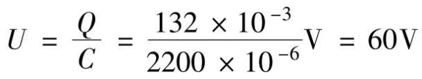
If the inverter resistance welding power source adopts numerical control, it can well compensate for the voltage drop of the filter capacitor and obtain more accurate welding energy; if it is controlled by analog IC, this voltage drop will affect each welding energy. If you need better welding energy accuracy, you need to increase the capacitance of the filter capacitor, such as 3300μF or even 4700μF.
How electrolytic capacitors work—The above is an analysis of the minimum capacitance required for the DC bus of the inverter resistance welding power supply.
8 How electrolytic capacitors work—Working mode of electrolytic capacitor in inverter resistance welding power supply with single-phase AC input
The output current of the inverter resistance welding power supply with single-phase AC input is relatively small, such as hundreds of amperes to thousands of amperes. The corresponding output power is mostly below 10kW, which is suitable for welding of small welding parts, such as thin plate welding or capacitor terminal welding. It works at a low load rate (even at 10% load rate) and works in a no-load state most of the time.
After rectification, the inverter resistance welding power supply with single-phase AC input requires filtering with a larger capacitance to smooth the rectified output current. This section only analyzes the working status of the filter capacitor.
Since smoothing the rectified output voltage after single-phase rectification requires a large-capacity capacitor, it is generally necessary to select the capacitance of the rectifier filter capacitor like a high-power switching power supply.
The ripple current flowing into the filter capacitor is the AC component of the current obtained by the full-bridge inverter from the DC bus and the 100Hz ripple current generated by the rectifier.
It can be seen from equation (10-8) that when the duty cycle of the bridge inverter is 0.5, the effective value of the switching frequency ripple current flowing into the filter capacitor is equal to the average value of the DC current. For an output current of 1000A, the average DC bus current is 16.5A, and the corresponding effective value of the switching frequency ripple current flowing into the filter capacitor is 16.5A.
When the rectified output voltage of the single-phase bridge rectifier circuit is 260V, for every 1W of power output, about 8mA of current flows through the filter capacitor. At half load (1000A/5V), the effective value of the 100Hz ripple current flowing into the filter capacitor is approximately 40A.
In this state, the total ripple current flowing through the filter capacitor is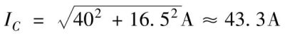
For an inverter resistance welding power source with 1000A/10V output, if five 470μF/400V electrolytic capacitors are selected in parallel, it can meet the requirements in the spot welding working mode with low duty cycle.
How electrolytic capacitors work—The above is an analysis of the working mode of the electrolytic capacitor in the inverter resistance welding power supply with single-phase AC input.
9 How electrolytic capacitors work—Working mode of electrolytic capacitor in inverter resistance welding power supply with three-phase AC input
9.1 How electrolytic capacitors work—Basis for selection of minimum capacitance
High-power inverter resistance welding power supply requires a three-phase AC input power supply mode. For example, the output current of a welding robot will reach 12kA or higher, and the full-load output power is as high as 100W!
Extremely high output currents require extremely high current rectifiers, i.e. special welding diodes. The initial reverse recovery data of this type of diode is suitable for rectangular wave voltage output with a switching frequency of 1kHz, so the switching frequency of high-power inverter resistance welding power sources is mostly 1kHz. Figure 13-19 shows the transformer nameplate of the inverter resistance welding power supply.
The transformer voltage ratio is 51:1. When the output current is 12kA, the peak current drawn by the full-bridge inverter from the DC bus is 235A. When the inverter operating duty cycle is 0.5, the average current drawn by the full-bridge inverter from the DC bus is 117.5A. The effective value of the AC current component of the switching frequency is 117.5A.
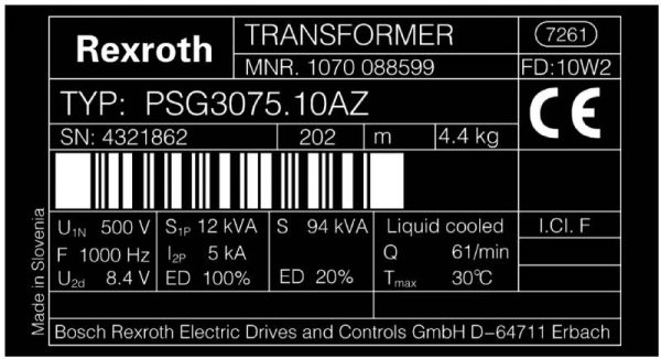 Figure 1-19 Transformer nameplate of inverter resistance welding power source
9.1.1 Minimum capacitance required for the switching process of the full-bridge inverter
When the operating duty cycle of the inverter is 0.5, the conduction time of the switch tube is 250μs, and the amount of charge during the conduction period of the switch tube is
Q=Iton=117.5×250×10m-6C=29375×10m-6C
If the DC bus voltage fluctuates 60V, the capacitance needs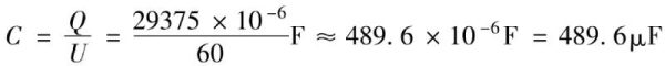 This will be a relatively large capacitance, and a three-phase bridge rectifier circuit connected in parallel with such a large capacitor will produce a very large ripple current.
9.1.2 Minimum capacitance required for 1/6 cycle of power frequency
The second factor that affects the minimum capacitance of the filter capacitor is that the working mode of the rectifier filter circuit requires the filter capacitor to supply power to the rectifier circuit output in discharge mode. In this mode, the capacitor’s voltage will drop. At this time, you need to know the discharge time of the filter capacitor. Figure 13-20 shows the waveform of the current flowing through the filter capacitor of the three-phase bridge rectifier circuit. The positive value is charging and the negative value is discharging.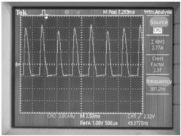 Figure 1-20 Current waveform of filter capacitor
As can be seen from Figure 1-20, the discharge time of the filter capacitor is close to 1.8ms, and the corresponding discharge charge amount is
Q=Iton=117.5×1.8×10m-3C=211.5×10m-3C
If the DC bus voltage fluctuates 60V, the capacitance needs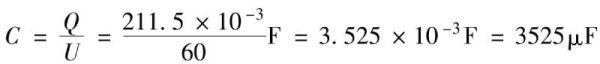
In practical applications, the capacitance of the filter capacitor must be at least this value.
9.2 Ripple current analysis
9.2.1 Ripple current flowing through the filter capacitor under half load condition
Take the output of 12kA/10V inverter resistance welding power supply as an example. The filter capacitor withstands the switching frequency ripple current and the ripple current generated by the rectifier filter circuit.
The switching frequency ripple current is analyzed as in Section 13.9.1. In the half-load state (output 12kA/5V), the effective value of the switching frequency ripple current is 117.5A.
In the same half-load state, in the three-phase 380V bridge rectifier/capacitor filter mode, the ripple current flowing into the filter capacitor for each 1kW output corresponds to about 1.7A, and 50kW corresponds to an effective current value of 85A.
The total current flowing through the filter capacitor is The above is the inverter resistance welding power supply working in spot welding (duty load rate 20%) working mode. If the inverter resistance welding power source works in continuous welding mode, the output current is roughly derated to about 45% of the “rated” output, as shown on the nameplate in Figure 1-19.
9.2.2 Ripple current flowing through the filter capacitor in continuous operation mode
The original design of the inverter resistance welding power supply is that it can work at full load when the temporary load rate is 20%, and the output current in continuous working mode is about 45% of the full load output current.
For an inverter resistance welding power supply with a full-load output current of 12kA, it can only output 5.4kA in continuous operating mode, and the corresponding switching frequency ripple current effective value is 53A.
The ripple current generated by the three-phase bridge rectifier circuit is 38.3A.
The total current flowing through the filter capacitor is
9.2.3 Ripple current flowing through the filter capacitor under full load condition
At full load, the inverter has a working duty cycle of 0.9. The inverter draws a peak current of 235A from the DC bus, the corresponding average current is 211.5A, the effective current value is 223A, and the ripple current flowing into the rectifier filter capacitor is
The ripple current generated by the rectifier filter circuit is 170A.
The total current flowing through the filter capacitor is 9.2.4 Summary
The inverter resistance welding power supply for welding robots is a high-power switching power supply with a constant current working mode. The rated power (current) is the working mode with a duty cycle of 20%, and the output power (current) in the continuous working mode is approximately 45% of the rated output power (current). In order to ensure the welding quality of resistance welding, the working duty cycle of the inverter resistance welding power supply is about 50% of the full load state. Therefore, the resistance welding operation is rarely at full load state in the spot welding mode.
In the spot welding mode, the inverter resistance welding power supply works in the half-load state, that is, the inverter operating duty cycle is 0.5. In the full-load state, the filter capacitor ripple current is the largest, which is 127% of the half-load state.
The ripple current of the filter capacitor in continuous operation mode is 45% of the ripple current of the filter capacitor in the half-load state.
How electrolytic capacitors work—The above is an analysis of the working mode of the electrolytic capacitor in the inverter resistance welding power supply with three-phase AC input.
How electrolytic capacitors work—Summarize:
How electrolytic capacitors work—It mainly talks about the electrolytic capacitors in the inverter arc welding power supply, the simple single-phase narrow voltage AC input inverter arc welding power supply, the electrolytic capacitors in the three-phase AC input inverter arc welding power supply, the working mode of the inverter resistance welding power supply, etc. . To learn more about electrolytic capacitors, please click:https://xuanxcapacitor.com