🍏The configuration of AC and DC capacitor filters in the converter station is mainly based on the harmonic components and reactive power requirements of the AC and DC sides of the converter station, and the configuration of the parallel capacitors is based on the reactive power requirements of the AC side of the converter station. During the working process of the converter, a large amount of reactive power will be consumed, and a large amount of harmonics will be generated on the AC and DC sides, which will harm the running electrical equipment and cause unfavorable factors such as communication interference. In order to maintain the reactive power balance of the system and eliminate harmonics, the converter station needs to be equipped with AC and DC filters. The DC filter is only used for filtering; the AC filter can also provide the capacitive reactive power required by the converter after meeting the filtering requirements. When the reactive power provided by the AC filter is not enough to meet the capacitive reactive power requirements of the converter, the remaining capacitive reactive power requirements are supplemented by the parallel capacitor device.
1 Harmonic components of the converter station
1.1 Overview
🍎The converter valve cyclically conducts and connects the AC and DC ends of the converter circuit according to a certain conduction sequence. When the converter operates in the rectification mode or the inverter mode, it will absorb capacitive reactive power from the AC system. Harmonic voltages and currents are generated on the AC and DC sides, resulting in power frequency sine wave distortion of the AC side voltage and current, and the DC side voltage and current are not smooth, but with ripples. The harmonic order is the ratio of the frequency of the harmonic to the fundamental frequency of the AC grid. Under ideal conditions, the harmonics generated by the commutation are called characteristic harmonics, and the harmonics generated by the converter are all related to the basic pulsating unit 6 pulsating the commutating unit.
🍐The principle of the 6-pulse converter is explained below. The wiring diagram of the principle of the 6-pulse converter unit is shown in Figure 1-1. The 6-pulse converter unit consists of a converter transformer, a 6-pulse converter, and the corresponding AC filter, DC filter and control and protection equipment.
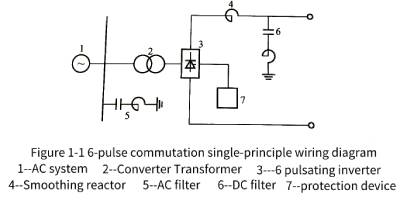
🍊The 6-pulse converter generates 6K±1 and 6K characteristic harmonics on the AC side and the DC side respectively (K is a positive integer). Therefore, a 6K±1-order AC filter needs to be configured on the AC side, and a 6K-order DC filter is usually required for overhead lines on the DC side. 6-pulse is the basic and the smallest unit that can constitute a converter. Usually, most DC systems use 12-pulse, that is, two basic 6-pulse converter units are connected in series on the DC side, as shown in Figure 1-2 Principle wiring as shown in the figure.
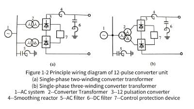
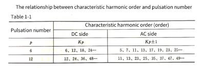
🍋The 12-pulse commutation unit is composed of two 6-pulse commutation units with a voltage phase difference of 30 on the AC side connected in parallel on the AC side (in series on the DC side). The 12-pulse converter generates characteristic harmonics of 12 K ± 1 and 12 K times on the AC side and the DC side, respectively. Therefore, only 12 K ± 1 and 12 K filters are required on the AC side and the DC side, respectively, thereby simplifying the filter device, reducing the floor space, and reducing the cost of the converter station. This is the main reason for choosing the 12-pulse commutator unit as the basic commutator unit. From this, it can be seen that the relationship between the characteristic harmonic order and the pulsation number is shown in Table 1-1.
🍌In the actual operation of the DC system, the operating conditions cannot be ideal, and the asymmetry of various parameters and controls during the operation of the converter and the saturation of the transformer in the system will generate non-characteristic harmonics. Non-characteristic harmonics are all other harmonics except characteristic harmonics. For example, the HP3 filter installed on the AC side of many converter stations is used to filter out the 3rd non-characteristic harmonics, and the 6/42nd order double-tuned filter installed on the DC side of some converter stations is used to filter out the DC side non-characteristic harmonics.
🍉There are two methods to reduce the harmonics generated during the commutation process of the converter, including increasing the pulsation number of the converter and installing a filter. The larger the pulsation number of the converter, the higher the number of characteristic harmonic currents, and the smaller the effective value of the harmonic currents. In general, the rms value of the n-th harmonic current is equal to 1/n of the rms value of the fundamental current. However, when the converter unit reaches more than 12 pulsations, the structure of the converter transformer is complicated, the manufacturing is difficult, and the economy is poor. Therefore, 12 pulsations is the best solution. When the 12-pulse converter is determined, in order to eliminate the characteristic and non-characteristic harmonics generated by the 12-pulse, it is necessary to install filters to limit the harmonics.
1.2 AC side characteristic harmonics
🍇(1) Characteristic harmonics on the AC side of the converter transformer. When the commutation angle u of the converter is not counted, the waveform of the line current on the valve side of the converter transformer (that is, the AC side of the converter device) is a series of equal time intervals, and positive and negative rectangular pulse waves appear alternately.
The expression of the converter transformer valve side line current is
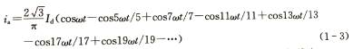
🍓It can be seen from formula (1-1) that when u=0, the valve side line current of the three-phase 6-pulse converter transformer contains only Kp±1 harmonics except the fundamental current, and the amplitude of the fundamental current is ![]() .The effective value of the fundamental wave current is the amplitude divided by the square root of 2 and the magnitude is
.The effective value of the fundamental wave current is the amplitude divided by the square root of 2 and the magnitude is ![]() .The effective value of the nth harmonic current is 1/n of the effective value of the fundamental wave current.
.The effective value of the nth harmonic current is 1/n of the effective value of the fundamental wave current.
🍈(2) The AC side line current of the converter transformer. When the connection mode of the converter transformer is Yy or Dd, and the transformation ratio is 1:1, the AC side line current is the same as the valve side current, and the expanded Fourier series is the same; when the converter transformer is replaced with Yd, the transformation ratio is 1: when the Fourier series expression of the AC side current is
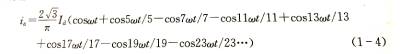
🍒(3) The AC side of the 12-pulse converter transformer is current, and the double-bridge 12-pulse converter unit is composed of two groups of 6-pulse converter units. One single-phase three-winding converter transformer can be installed, and two single-phase double-winding converter transformers can be installed. Winding converter transformer. When the winding connections are Yy and Yd respectively, and the transformation ratio is 1:1 and 1:, the total current expression of the double-bridge 12-pulse AC side is expressed as
The effects of the commutation angle u and the delay angle a on the resonant current are as follows:
1) When the commutation angle u increases, the resonant current decreases. The higher the harmonic order, the faster the harmonic current decreases.
2) Within a certain range, the decreasing speed of the resonant current also increases with the increase of the u angle.
3) When the harmonic current is around u=360 degrees/n, the harmonic current drops to the minimum value, and then increases slightly.
4) If U is a fixed value, the variation of each harmonic current with different angle a is small.
5) In any case, the effective value of harmonic current will not exceed 0.78Id/n.
1.3 DC side characteristic harmonics
🥭The DC side characteristic harmonic calculation is usually based on the DC voltage curve, using the Fourier series to expand, to obtain the DC component and the sine and cosine components of each harmonic, so as to obtain the harmonic current of each order; The equivalent circuit corresponding to the harmonic, the harmonic current is obtained from the harmonic voltage and impedance.
(1) The expression of the harmonic voltage on the DC side of the converter is:
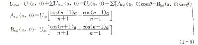
🍍In the formula: Ud(a, o) is the DC component of the harmonic voltage; Udn(a, o) is the n-th harmonic voltage; a is the delay angle; it is the no-load DC voltage when a=0.
(2) The expression of the harmonic current on the DC side is:
![]()
where: is the load impedance of the converter; R is the load resistance of the converter; , is the inductance of the smoothing reactor; L is the internal inductance of the converter.
1.4 Non-characteristic harmonics of converter station
🥝The operating conditions of the DC transmission system cannot be ideal in practice, and these non-ideal factors lead to the generation of non-characteristic harmonics in the system.
(1) Causes of non-characteristic harmonics on the AC side of the converter station. There is ripple current in DC current; ripple voltage exists in AC voltage; AC fundamental voltage is not necessarily strictly symmetrical, that is, there is negative sequence voltage; there is phase-to-phase difference in converter transformer impedance; Yy group 6 pulsating converters and Yd group 6 There may be differences in the firing angle of the pulsating converters; the commutation voltages of the Yy group converters and the Yd group converters are different due to the different transformation ratios of the converter transformers; the firing pulses are difficult to be completely equidistant.
(2) Causes of non-characteristic harmonics on the DC side of the converter station. There are various waves in the AC voltage; the leakage reactance and transformation ratio of the Yy group converters and the Yd group converters are not equal; any operating parameters of the two-pole converters that constitute a converter station are not equal; the three-phase leakage reactance of the converter transformer unbalanced.
1.5 Other harmonic sources on the AC side of the converter station
🍅For the AC filter of the converter station, in addition to the characteristic harmonics generated by the converter and the non-characteristic harmonics generated by different equipment parameters and operating parameters of the converter station, there are also background harmonics of the AC system. and harmonics from saturation of converter transformers or other transformers.
(1) Background harmonics. With its own AC power system network and various user terminals (such as traction stations, electrified railway loads, various industrial motor loads, miniaturized rectifier load terminals, etc.), the background harmonics are brought to the AC network by these loads. Another important factor that generates background harmonics is the low-order harmonics caused by the saturation of the AC system transformer. This needs to be solved by selecting the rated tap position of the transformer and optimizing the operating voltage level of the AC system. The background harmonics of the system are very harmful to the power grid, especially for the converter stations with a large number of AC filters. The main reason is that these background harmonics of the power system have a tendency to flow to the nearby converter stations. Magnets absorb these harmonics, so a reasonable determination of these background harmonics has a big impact on the economical operation of the filter.
(2) Harmonics generated by transformer saturation. The transformers referred to here include both ordinary power transformers and converter transformers for DC converter stations. The saturation of converter transformers and ordinary power transformers will generate harmonics, which also belong to the category of background harmonics. There are three situations that cause converter transformer saturation in the converter station: (1) During the voltage recovery process after the transformer is put in and the short-circuit fault is removed, the transient saturation generated by the converter transformer produces transient stress on the filter, and this stress affects the filter. The component ratings of the filter do not generally play a role and are therefore usually not taken into account in filter calculations. ② The voltage of the AC busbar increases. For a properly designed flow system, the tap of the converter transformer always increases with the increase of the AC voltage, and there will be no obvious saturation phenomenon. ③ The DC component stored in the converter transformer may run in a supersaturated state for a long time, and the resulting harmonic current may be a long-term burden on the AC filter.
2 Types of filters
🍆AC and DC filters include conventional passive AC and DC filters and active AC and DC filters. In addition to the above two kinds of AC filters, there are continuously adjustable AC filters. That is to say, there are 3 types of AC filters: passive, active, and continuously adjustable, and there are 2 types of DC filters: passive and active.
🍭Passive filters are composed of resistors, capacitors and inductors, and have low impedance within the specified range of 1 or 2 harmonic frequencies or under the high-pass frequency band, so that most of the harmonic current generated by the converter flows into the filter. From reducing the harmonics injected into the AC system to meet the requirements of reducing harmonic content. There are three types of AC filters widely used in DC converter stations: single-tuned filter, double-tuned filter and two-order high-pass filter. At present, new DC converter stations tend to use double-tuned high-pass filter and multi-tuned high-pass filter. .
🔮Active filters have various types such as magnetic flux compensation, harmonic injection and DC ripple injection. By detecting the current and voltage in the line, the corresponding harmonic current is analyzed and calculated, and then the same harmonic current is generated. , Compensation current in opposite directions, the two cancel each other to achieve the purpose of eliminating harmonics. It can dynamically control harmonics and reactive power, and is not affected by frequency and is not prone to resonance, but its main circuit generally uses fully-controlled power electronic devices, while the current technical level of fully-controlled devices. The capacity of the active filter is small and the operating frequency is not high, so the compensation capacity of the active filter is limited, which is a practical technology to be further developed.
🌟Continuously adjustable AC filter is a filter type that continuously adjusts the inductance of the reactor by using the control signal on the basis of the passive filter, so that it is always in an ideal tuning state. At present, passive AC and DC filters are basically used in domestic DC transmission projects. Passive filter technology has been very mature in design, manufacture, debugging, installation and operation. Active AC and DC filters and continuously adjustable AC filters are only used in individual DC transmission projects. This chapter only describes passive AC and DC filters.
2.1 Classification of passive filters
✨The passive filter in the DC transmission system refers to the LC passive filter. LC passive filters can be divided into tuned filters and damped filters. Tuned filters for converter stations include single-tuned filters, double-tuned filters, and triple-tuned filters; damping filters include first-order high-pass filters (not commonly used), second-order high-pass filters (basically not used at present), third-order high-pass filters High-pass filter, C-type damping filter (derived from a third-order filter). The easiest way to determine the filter order is to judge according to the number of nonlinear components (capacitors and inductors are nonlinear components).
2.2 Impedance characteristics of passive filter
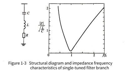
💥A single-tuned filter is a filter circuit composed of components such as resistor R, inductor L, and capacitor C in series. It has the smallest impedance at a certain low-order harmonic (or near the low-order harmonic) frequency. device. For the low-order filter frequency, there is one filter branch, as shown in Figure 1-3, where the frequency when the second-order circuit resonates is 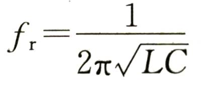
🌈The double-tuned filter has very low impedance to two low-order frequencies at the same time, which can absorb (filter out) two characteristic harmonics at the same time. It is actually equivalent to two single-tuned filters, and has two RLC branches in parallel, as shown in Figure 1-4.
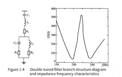
The above two types are very commonly used in DC converter stations, such as converter station HP3, HP11/13, HP24/26 filters, which are typical single- and double-tuned filters.
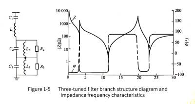
☀️The three-tuned filter has very low impedance to 3 kinds of low-frequency harmonics at the same time, which can absorb (filter out) 3 kinds of characteristic harmonics at the same time. It is actually equivalent to three single-tuned filters, and has three RLC parallel branches, as shown in Figure 1-5. Three-tuned tuners have also been used in some domestic converter stations, but they are not as common as single-tuned and double-tuned applications.
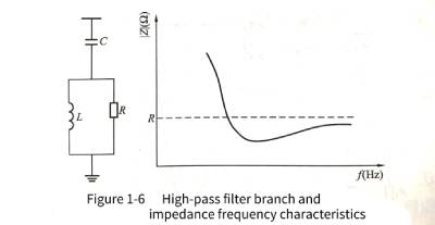
🌼The damping filter is realized by connecting a damping resistor in parallel with the filter reactor. Compared with the single-tuned filter, there is an additional parallel resistor on the physical element. Functionally, the damping filter has a wide frequency range near the resonance frequency. The filter impedances are all at low values and are not sensitive to detuning because their resonant frequency is a frequency band. In the higher frequency range, the filter impedance approaches the limit determined by the damping resistor, as shown in Figure 1-6.
🌻The damping filter can simplify the filter branch, and its purpose is to facilitate switching when the operating mode changes and the required filter capacity is different. Since the rated parameters of the HVDC system are of the same order of magnitude as the short-circuit level of the system, the possibility of low-order harmonic resonance between the system and the filter capacitors is increased. As for whether the series or parallel resonance occurs, it depends on the low-order harmonics. The source is in the AC system or in the converter station, and the damping filter can better solve this problem.
🌞Advantages of damping filters, filter performance and load are insensitive to temperature, system frequency offset and allowable deviation of components; a wide range of harmonic frequencies can be filtered out, reducing grouping by harmonic order The investment cost of tuning also reduces the corresponding floor space; it reduces the workload of on-site debugging and maintenance, and basically no on-site tuning work is required; it can also absorb and filter a considerable part of non-characteristic harmonics; For station reactive power control, this filter grouping is less, not only economical investment, but also easy to control.
🌝Tuning the filter in practical applications avoids causing detuning of the filter. Detuning means that the low-impedance circuit path of the original design corresponding frequency changes (does not match the original frequency). There are many factors that cause the detuning, mainly including the frequency deviation of the AC capacitor; the deviation of the component data from the specified value due to the temperature change; the fuse of the internal capacitor element of the capacitor is blown, which causes the filter capacitance value to change. To avoid detuning of the tuning circuit due to the above reasons, a low-value series resistor is usually added to the tuning filter to widen the tuning range.
🍄In addition to the categories mentioned above, filters can also be divided into series filters, parallel filters and series-parallel filters (combination of the two) according to the series-parallel connection with the system. A series filter is a series circuit with high impedance at harmonic frequencies, which prevents entry from the converter into the grid or DC line. A parallel filter is a parallel circuit with very low impedance at harmonic frequencies, allowing harmonics to flow into the filter without entering the grid or DC line. Compared with the series filter, the parallel filter has many advantages. For example, the series filter must pass all the current of the main circuit and must be insulated with full voltage to the ground; while one end of the parallel filter can be grounded, and the current passing through it is only The harmonic currents filtered out by it and a much smaller fundamental current than in the main circuit, the insulation requirements are also relatively low. Parallel filters are generally much cheaper than series filters with the same effect, and parallel filters are also widely used in converter stations.
3. Configuration principles and differences of AC and DC filters
3.1 AC filter configuration principle
🎄In addition to filtering out the harmonic current generated by the converter, the AC filter configured in the converter station also provides the required part of the fundamental wave reactive power to the converter. Generally, there are the following configuration principles; in the converter stations that have been operating in my country, the rated voltage level of the filter is the same as the voltage level of the busbar on the AC side of the converter; the corresponding single-tuned, double-tuned or triple-tuned filters are reasonably configured, but The types should not be too many; in the case of meeting the requirements of the DC converter station to filter out harmonics, the filters are grouped with a small number of cores. When the filter cannot meet the reactive power consumption of the converter, use parallel capacitor groups as much as possible to supplement it; when all filters are put into operation, they should meet the performance requirements of various harsh operating modes such as continuous overload of the DC system; any one When the group filter is out of operation, it should meet the requirements of the operating conditions of the system; when the DC converter station is running with unlocked power, the input capacity of the filter should be the smallest.
3.2 DC filter configuration principle
🌷As mentioned earlier, theoretically, a 12-pulse converter only generates 12K harmonic voltages on the DC side. However, in actual operation, due to various asymmetric factors, the converter will generate non-characteristic harmonics on the DC side. Different DC converter stations have different configurations of non-characteristic harmonic filters. The filtering of harmonics is the same at each converter station. Through practical engineering experience, some non-characteristic harmonics with lower order generated by the stray capacitance of the converter transformer have larger amplitudes, and a larger wave feeder capacity is required to filter them out. The DC filter configuration should fully consider the amplitude of each harmonic and its proportion in the equivalent interference current (that is, the coupling coefficient and weighting coefficient of each harmonic current when calculating its equivalent interference current). In addition, the two DC poles of the same converter station have correspondence, so the two poles should be equipped with the same DC filter.
🐾The DC filter configuration scheme commonly used in domestic conventional large-scale DC transmission systems is as follows: install one or two parallel double-tuned filters <or three-tuned filters between the DC high-voltage busbar and the neutral busbar of each pole of the converter station. 〉Used to filter out the characteristic harmonics of the DC side, and configure different DC filters to filter out the non-characteristic harmonics according to different DC engineering designs; for the characteristic harmonic filters of the DC side, the center tuning frequency should be higher for the harmonic amplitude. The characteristic harmonics of the 12-pulse converter, and the high-order harmonics that have a greater impact on the equivalent interference current; for the non-characteristic harmonics with low order, a neutral bus can be connected between the low-voltage side of the 12-pulse converter and the ground. Bus impulse capacitors, so that there is no need to specially install low-order harmonic filters to save investment.
3.3 Difference between DC filter and AC filter
🌞The DC filter is usually connected as a parallel filter between the pole bus and the neutral bus of the converter station. The primary circuit structure of the DC filter is similar to that of the AC filter, and there are also various circuit structures. The commonly used ones are with or without high-pass The characteristic single-tuned, double-tuned and three-tuned filters have a circuit structure similar to that of an AC filter. Although DC filters have many things in common with AC filters, there are also some differences:
(1) The AC filter provides power frequency reactive power to the converter station, so its reactive power capacity is usually designed to be larger than the reactive power setting capacity required by the filtering characteristics, while the DC filter does not need this requirement.
(2) For the AC filter (parallel capacitor), the voltage acting on the high-voltage capacitor can be considered to be evenly distributed on a plurality of capacitors connected in series. For the DC filter, the high-voltage capacitor acts to isolate the DC voltage and has a high tolerance. of the DC voltage. Due to the existence of the DC leakage resistance, if no measures are taken, the DC voltage will be unevenly distributed along the leakage resistance. Therefore, a voltage equalizing resistor must be installed in parallel inside the DC filter capacitor unit.
(3) The impedance range of the AC system connected in parallel with the AC filter is relatively large at a certain frequency. Under certain power grid conditions, such as switching of the AC line, local faults of the power grid, etc., the AC filter capacitor and the AC will be caused. Resonance between system inductances. Therefore, damping measures are required even in precisely tuned (band-pass tuned) AC filter circuits. The impedance of the DC side of the converter station is generally constant, thus allowing the use of an accurately tuned (band-pass tuned) DC filter. The determination of the circuit structure of the DC filter should be based on the equivalent interference current generated by the DC line. Since the amplitude of the characteristic harmonic current is the largest, the circuit structure of the DC filter should be consistent with these harmonics (that is, the harmonic order is 12). , 24, 36– harmonics) to match.
(4) The high-voltage capacitor is the most valuable component in the DC filter equipment, because it must be designed as a capacitor that can withstand a high DC voltage. The difference in the cost of the capacitor is also the difference between the AC filter and the DC filter. a significant difference. One of the main means to reduce the investment cost of DC filters is to design the filters as double-tuned or multi-tuned harmonic filter circuits with common high voltage capacitors. Sometimes, in order to filter out the non-characteristic harmonics on the DC side and avoid installing high-cost DC filters that withstand high DC voltages, a filter capacitor is usually installed between the neutral point of the converter station and the ground. The function of installing this capacitor is to provide a low-impedance channel for the harmonic current whose main component is the 3rd harmonic on the DC side. Furthermore, as mentioned above, due to the presence of stray capacitance to ground in the converter transformer winding, it provides a channel for DC harmonics, especially lower-order DC harmonic currents, so the neutral point should be determined for such harmonics. capacitor parameters. Generally speaking, the selection range of the capacitance value of the capacitor should be ten microfarads or several millifarads, and at the same time, parallel resonance with the inductance of the grounding line at the critical frequency should be avoided.