Most of today’s electrolytic capacitors are used in power frequency or high-frequency rectification and filtering of power electronic circuits, power supply bypass with high ripple current, etc. Therefore, in addition to the traditional performance of capacitors: rated voltage, capacitance, loss factor, leakage current, modern power electronics technology and future radio frequency power electronics technology have put forward new performance requirements for electrolytic capacitors, mainly including ripple current endurance, Equivalent series resistance, equivalent series inductance and other parameters.Therefore, the performance analysis of electrolytic capacitors is the main content of this chapter.
1 Performance Analysis of Electrolytic Capacitors– Equivalent circuit of electrolytic capacitor
Electrolytic capacitors can be represented by different equivalent circuits under different working conditions. The equivalent circuit that can better reflect the characteristics of aluminum electrolytic capacitors is shown in Figure 1-1
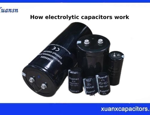
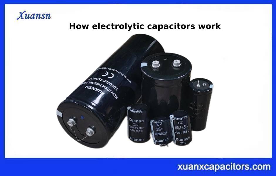
Figure 1-1 performance analysis of electrolytic capacitors
R1, R, R3, C1, C2, L and VD in Figure 1-1a are respectively the resistance of the electrode and the terminal, the resistance of the electrolyte, the insulation resistance of the oxide film medium (after being damaged by the manufacturing process), and the anode foil. capacitance, the original oxide film capacitance of the cathode foil, the inductance caused by the electrodes and lead terminals, and the diode indicating the polarity of the anodized film.
Therefore, a reverse voltage of an electrolytic capacitor exceeding 1.5V will cause a large leakage current, much like a diode conducting forward. In this case, the electrolysis effect will produce hydrogen, which will increase the internal pressure and burst the pressure relief device. At the same time, the reverse voltage will also destroy the aluminum oxide film, causing the electrolytic capacitor’s withstand voltage to drop sharply until it fails. This is why electrolytic capacitors cannot be used with reverse polarity.
The original oxide film of the cathode foil is very thin, with very small withstand voltage, and little remains under the action of negative polarity voltage. Therefore, the capacitance C2 of the original oxide film of the cathode foil can be regarded as a short circuit.
The equivalent circuit for general applications mostly uses a simplified equivalent circuit, that is, combining R1 and R2 in Figure 1-1a, combining C1 and C2, ignoring R3: (the leakage current is very small) and VD (no reverse voltage is applied in normal applications) , a commonly used equivalent circuit is obtained, as shown in Figure 1-1b. In Figure 1-1b, neither RESR nor L is expected to exist in the capacitor. They are parasitic parameters of the aluminum electrolytic capacitor. The parasitic parameters of the aluminum electrolytic capacitor have a great impact on its performance.
The above is about the performance analysis of electrolytic capacitors—equivalent circuit of electrolytic capacitors
2 Performance Analysis of Electrolytic Capacitors – Equivalent series resistance and its characteristics
Begin by analyzing the Equivalent Series Resistance (ESR). For the convenience of analysis, Figure 1-1 can be simplified into an equivalent circuit of a capacitor and ESR in series, as shown in Figure 1-2. Among them, the resistance of the electrolyte is the main part of ESR. Low ESR aluminum electrolytic capacitors actually use low resistivity electrolytes.
The measurement conditions of ESR are to use a maximum AC signal voltage with an effective value of 1V and a 120Hz power supply with no forward bias voltage in an environment of 25°C to power an equivalent series circuit of aluminum electrolytic capacitors, and measure the resistance in the circuit. Measurement
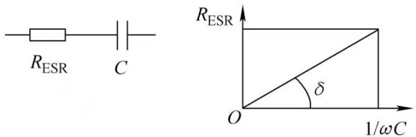
Figure 1-2 Simplified equivalent circuit of electrolytic capacitor
For aluminum electrolytic capacitors used in general applications, most manufacturers do not provide ESR data, but they do provide this data for low-ESR aluminum electrolytic capacitors used in switching power supplies or pin-type aluminum electrolytic capacitors with relatively large capacitance.
The main reason why most aluminum electrolytic capacitor manufacturers do not provide ESR data is: compared to capacitors of other media, the ESR of aluminum electrolytic capacitors is too large. For example, the ESR of a 1uF/16V ordinary aluminum electrolytic capacitor is generally around 20Ω; the ESR of a 100F aluminum electrolytic capacitor is between 1.5~2Ω. Just imagine, writing such data in the data sheet will definitely affect the user’s confidence in using aluminum electrolytic capacitors. Therefore, in a sense, the application of aluminum electrolytic capacitors is a helpless choice.
In the application of switching power supply, it is often found that when ordinary aluminum electrolytic capacitors are used, the output voltage ripple and spike suppression effect is very poor. The main reason is that the ESR of conventional aluminum electrolytic capacitors is “too large”. In high-frequency applications, electrolytic capacitors behave like resistors to AC circuits. Therefore, to obtain a better high-frequency filtering effect, the ESR of the filter capacitor should be reduced as much as possible, that is, a low-ESR aluminum electrolytic capacitor should be selected. The ESR of low-ESR aluminum electrolytic capacitors can generally be an order of magnitude or more lower than that of ordinary aluminum electrolytic capacitors. In order to obtain low ESR aluminum electrolytic capacitors, a low resistivity electrolyte is used. If it is also necessary to reduce the equivalent series inductance, adopt low parasitic inductance measures in the winding process and electrode lead-out of the aluminum electrolytic capacitor
2.1 Performance Analysis of Electrolytic Capacitors-Equivalent series resistance
ESR is the circuit equivalent of the heating effect produced when AC current flows through an electrolytic capacitor.
Why not a parallel equivalent resistance? Any capacitor will have a parallel equivalent resistance, that is, the impact of leakage current on the circuit. Heating caused by leakage current is mainly related to the capacitor terminal voltage and has nothing to do with the flowing AC current. The heat generated by the electrolytic capacitor caused by AC current flowing through it is ESR from the circuit equivalent point of view, whether it is the volume resistance of the electrolyte or the equivalent resistance of the lattice vibration caused by the aluminum oxide film under the action of AC current, which results in heat generation.
The equivalent series resistance of an aluminum electrolytic capacitor can be divided into two parts: when the aluminum oxide film flows through AC current, the polar lattice of the solid aluminum oxide film vibrates with the AC electric field to produce a heating electrical effect, and the equivalent resistance part of the electrolyte.
These two types of equivalent series resistance have different causes, so the resistance characteristics will have different effects in different frequency bands.
2.2 Performance Analysis of Electrolytic Capacitors-ESR frequency characteristics
Unlike the resistance characteristics of metals, the ESR of aluminum electrolytic capacitors changes with frequency. Its changing pattern is shown in Figure 1-3.
As can be seen from Figure 1-3, the ESR frequency characteristics of electrolytic capacitors with different rated voltages are different, but the general trend is the same, that is, as the frequency increases, the ESR value decreases. The higher the rated voltage, the ESR decreases. The frequency changes are more obvious.
Considering that most electrolytic capacitors are used for rectification and filtering, even in half-wave rectification, the ripple current frequency flowing into the electrolytic capacitor is 50Hz. Therefore, the frequency starting point of the ESR frequency characteristic is 50Hz and the highest frequency is 100kHz.
In the range of 50~200Hz, the ESR changes relatively drastically. It can be considered that the ESR of the aluminum oxide film decreases sharply as the ripple current frequency increases.
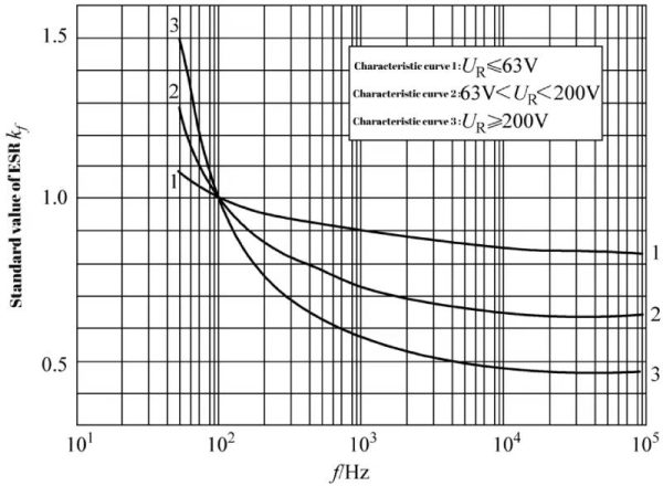
Figure 1-3 RIFA’s PEF356 series electrolytic capacitor ESR frequency characteristic curve
As the ripple current frequency increases, the ESR value of the aluminum oxide film decreases significantly, its proportion in the total ESR of the aluminum electrolytic capacitor gradually decreases, and the proportion of ESR in the electrolyte part becomes larger and larger. Therefore, as the frequency increases, the decreasing trend of electrolytic capacitor ESR slows down. When the frequency is above 10kHz, the ESR of the electrolyte part is close to the ESR of the electrolytic capacitor, so that the ESR of the electrolytic capacitor no longer changes with frequency.
Figure 1-3 also shows that the ESR ratio generated by the aluminum oxide film of high-voltage electrolytic capacitors is much larger than that of low-voltage electrolytic capacitors, causing the ESR of high-voltage electrolytic capacitors to change drastically in the low frequency band.
2.3 Performance Analysis of Electrolytic Capacitors-ESR temperature characteristics
The ESR of an electrolytic capacitor changes with temperature, and its temperature characteristic curve is shown in Figure 1-4.
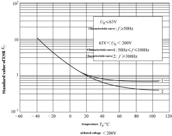 Figure 1-4 Temperature characteristic curve of ESR of RIFA’s PEF356 series electrolytic capacitors
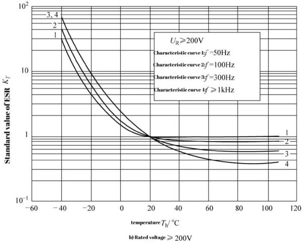 Figure 1-4 Temperature characteristic curve of ESR of RIFA’s PEF356 series electrolytic capacitor (continued)
The above is about the performance analysis of electrolytic capacitors—equivalent series resistance and its characteristics
3 Performance Analysis of Electrolytic Capacitors-equivalent series inductance
Various electronic components and even the wires themselves have parasitic inductance, and electrolytic capacitors are no exception.
The parasitic inductance of the electrolytic capacitor is connected in series with the ESR and the ideal capacitor in the capacitor equivalent circuit, so the parasitic inductance of the capacitor is also called the equivalent series inductance (ESL).
Since electrolytic capacitors are wound, wound inductance cannot be avoided, and the inductance produced by electrolytic capacitors is much larger than non-inductive film capacitors with gold-sprayed ends.
The parasitic inductance of an electrolytic capacitor with multiple groups of conductor bars is lower than that of a single group of conductor bars or lead-pin electrolytic capacitors. The parasitic inductance of electrolytic capacitors with “middle” guide pins or “middle” guide bars is lower than that of electrolytic capacitors with offset guide bars or offset guide pins. The reason is that the current in the center guide pins flows to both sides of the filter, which will Offset part of the winding inductance. Multiple guide bars reduce the filtering length between the two guide bars, and the aluminum foil flowing from the guide bar to both sides of the guide bar will also offset part of the winding inductance.
The ESL of electrolytic capacitors using the negative electrode extension process is lower than that of electrolytic capacitors without negative electrode extension. The reason is that all negative electrode parts are “short-circuited” with the negative electrode foil by using negative electrode extension. Although the short-circuit effect is not ideal, it is still a short circuit. If the entire positive foil is also “shorted”, the ESL of the wound electrolytic capacitor will be greatly reduced. The resonant frequency of an electrolytic capacitor with a capacitance of 100μF may increase to 100kHz.
ESL affects the current distribution on the aluminum foil. The longer the aluminum foil, the greater its impact. The narrower the aluminum foil, the greater its impact. The higher the ripple current frequency, the greater its impact. Figure 1-5 shows the current distribution diagram of the aluminum foil of the electrolytic capacitor.
The upper picture of Figure 1-5a shows the position of the aluminum foil and the guide pin. The guide pin is located in the middle of the aluminum foil. The lower picture of Figure 1-5a shows the distribution of current on the aluminum foil. Obviously, the current in the contact part between the guide pin and the aluminum foil is the largest, and the current on each side is half of the current flowing into the capacitor. As the foil gets farther and farther away from the guide pin, the current becomes smaller and smaller until the foil terminal current drops to zero.
If the guide pin needs to be set on one side of the aluminum foil, as shown in Figure 1-5b, it is obvious that the current distribution on both sides of the guide pin is different. The current on the long side of the aluminum foil is large, and the current on the short side of the aluminum foil is small. Obviously, when the guide pin is in the middle of the aluminum foil, the performance of the capacitor is the best. If the guide pin deviates from the center of the aluminum foil, the performance of the capacitor will decrease. The farther the guide pin is from the middle of the aluminum foil, the worse the performance. The performance of the capacitor is best when the guide pin is located at one end of the aluminum foil. Difference
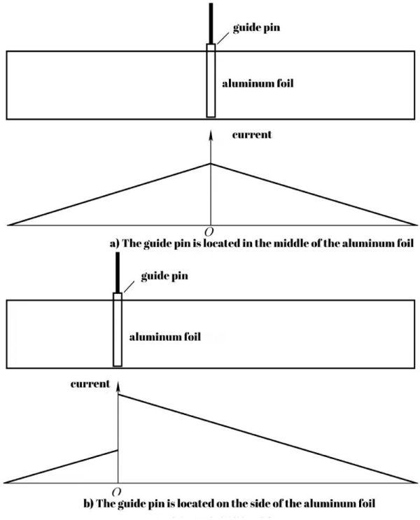 Figure 1-5 Schematic diagram of current distribution of electrolytic capacitor aluminum foil
Since electrolytic capacitors are wound, winding inductance will inevitably occur. The aluminum foil current affected by ESL will be more concentrated near the guide pin or guide bar, and the higher the frequency, the more serious it will be. The reason is that high-frequency ripple current flows through the ESL, producing a voltage drop on the ESL, and this voltage drop U will hinder the current flow to the aluminum foil at the far end of the guide pin or guide bar. The voltage drop is
U=2πfLESLI
For example, when the ESL is 10nH and the frequency is 100kHz, an impedance of 6.28mΩ will be produced. What needs to be clear is that the ESR of a 1000μF high-frequency low-resistance electrolytic capacitor is only 30mΩ, while the ESL of a 1000μF electrolytic capacitor is much more than 10nH!
When the guide pin deviates greatly from the center of the aluminum foil, under normal (120Hz) test conditions, the capacitance, leakage current, loss factor, ESR and other parameters are not much different from those of the capacitor with the guide pin located in the center of the aluminum foil, and they are all good products. However, there will be a big difference in the high temperature load life test, and the high frequency characteristics are also different. Therefore, in practical applications, users should try to avoid products with guide pins far away from the center of the aluminum foil.
The above is the performance analysis of electrolytic capacitors—equivalent series inductance
4 Performance Analysis of Electrolytic Capacitors-impedance frequency characteristics of electrolytic capacitors
4.1 Performance Analysis of Electrolytic Capacitors-Performance Analysis of Electrolytic Capacitors-The relationship between the impedance of lead-pin electrolytic capacitors, frequency and temperature
The resistance of the electrolyte is the main part of the ESR of the aluminum electrolytic capacitor, and the resistivity of most electrolytes decreases as the temperature increases, so the ESR of the aluminum electrolytic capacitor also decreases as the temperature increases. The relationship between impedance frequency characteristics and temperature of a certain 100μF/63V and 47μF/350V aluminum electrolytic capacitor is shown in Figure 1-6. The figure shows the impedance frequency characteristics at typical temperatures from -40 to 85°C.
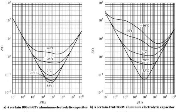 Figure 1-6 Impedance frequency characteristic curve of aluminum electrolytic capacitor
The lowest value of each curve in Figure 1-6 can be considered as the ESR value. It can be seen from the figure that the ESR of the 100μF/63V aluminum electrolytic capacitor is close to 1.5Ω at -40℃ and drops to 0.5 at -25℃. Ω, dropped to 0.1Ω at 0℃, 0.05Ω at room temperature of 20℃, and the ESR at the maximum operating temperature of 85℃ is the lowest, 0.04Ω; the ESR of the 47μF/350V aluminum electrolytic capacitor at -40℃ is close to 6Ω , dropped to 3Ω at -25℃, 1.2Ω at 0℃, 0.4Ω at room temperature 20℃, and the lowest ESR at the maximum operating temperature of 85℃, 0.06Ω. It can be seen that the ESR decreases by 35% to 50% from 20°C to 85°C, but the ESR increases significantly at low temperatures, and the ESR increases by about an order of magnitude from -40°C to 0°C. From the highest operating temperature to the lowest operating temperature, the ESR increases by 40 to 100 times.
Typically, the ESR of aluminum electrolytic capacitors changes relatively little with frequency. ESR values range from 0.002Ω for large capacitance bolt terminal aluminum electrolytic capacitors to 20 to 30Ω for very small capacitance leaded aluminum electrolytic capacitors.
The resonant frequency of the electrolytic capacitor shown in Figure 1-6a is about 70kHz, and the LC resonant frequency formula is
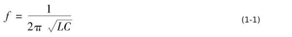
The 100μF/63V aluminum electrolytic capacitor is a lead-pin electrolytic capacitor, and its ESL can be calculated according to formula (1-1) to be approximately 45nH.
ESL can also be found using the slope of the inductive section of the electrolytic capacitor. It is also a 100μF/63V lead-pin aluminum electrolytic capacitor. The impedance corresponding to 400kHz is about 0.1Ω, the impedance corresponding to 4MHz is about 1Ω, and the impedance corresponding to 40MHz is about 10Ω. Every time the frequency increases by one order of magnitude, the impedance also increases by one order of magnitude. Since the capacitive reactance of 100μF is very different from the inductive reactance in the range of 4 to 40MHz, it can be approximately considered that the curve in this frequency band is the curve of inductance and ESR. That is to say, the impedance at 40MHz frequency is about 11Ω, and the ESR is about 0.04Ω. According to the impedance relationship between inductor and resistor in series
![]()
have to
![]()
Also based on
![]()
The results of estimating ESL using the resonant frequency or estimating the ESL using the slope of the inductive section of the impedance frequency characteristic curve are very close.
The corresponding impedance of the 47μF/350V aluminum electrolytic capacitor in Figure 1-6b is 20Ω at a frequency of 60MHz. According to equation (1-4), it can be concluded that the ESL is
![]()
4.2 The relationship between the impedance of pin-type electrolytic capacitors, frequency and temperature
The impedance frequency characteristic curve of the pin type electrolytic capacitor B43504 is shown in Figure 1-7.
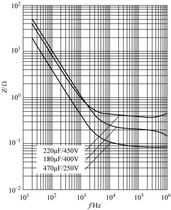 Figure 1-7 Impedance frequency characteristic curve of electrolytic capacitor B43504
The resonant frequency point and inductance curve part cannot be seen in Figure 1-7, so the ESL of the electrolytic capacitor cannot be obtained using the impedance frequency characteristic curve. You can read the datasheet to see the ESL of this series of electrolytic capacitors, which is about 20nH.
4.3 The relationship between the impedance of bolt-type electrolytic capacitors, frequency and temperature
Take the bolt-type electrolytic capacitor B43560 as an example. It is given in the data sheet: an electrolytic capacitor with a diameter of 51.6mm has an ESL of approximately 15nH, and an electrolytic capacitor with a diameter greater than or equal to 64.3mm has an ESL of approximately 20nH. If ESL is not given in the data sheet, it needs to be calculated from the impedance frequency characteristic curve.
The impedance frequency characteristic curve of B43560 is shown in Figure 1-8.
The ESL of the 15000μF/350V and 6000μF/450V electrolytic capacitors in Figure 1-8 is basically the same. The corresponding impedance at 1MHz frequency is about 0.1Ω, and the corresponding ESL is 3900μF/350V electrolytic capacitor. The ESL of the 3900μF/350V electrolytic capacitor is basically the same, and the corresponding impedance at 1MHz frequency is The impedance is about 0.08Ω, and the corresponding ESL is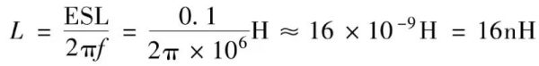
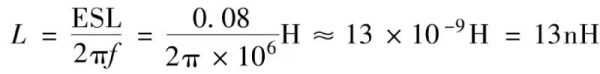
The ESL of the 3900μF/350V electrolytic capacitor is basically the same. The corresponding impedance at 1MHz frequency is about 0.08Ω, and the corresponding ESL is
Obviously for large electrolytic capacitors, the ESL of 16nH and 13nH is definitely very low, even lower than the ESL of film capacitors of the same size!
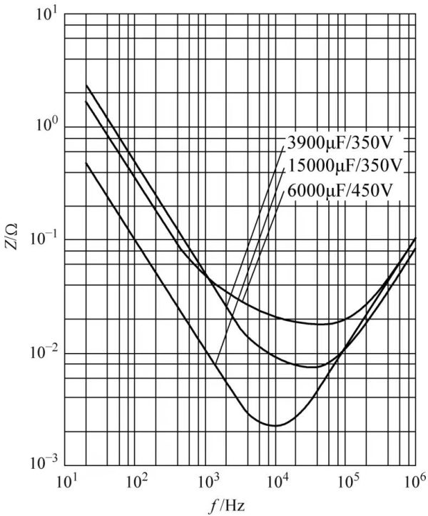 Figure 1-8 Impedance frequency characteristic curve of B43560
Since the capacitance of the 15000μF/350V electrolytic capacitor is significantly larger than that of the 6000μF/450V electrolytic capacitor, although the ESL of the two electrolytic capacitors is basically the same, the resonant frequency of the former (about 100kHz) is significantly lower than the resonant frequency of the latter (200~250kHz ), judging from these two curves, the traditional saying that large capacitors filter low frequencies and small capacitors filter high frequencies is inappropriate for the current level of components. A 15000μF electrolytic capacitor has the same impedance as a 6000μF electrolytic capacitor in the high frequency range, so the filtering performance is also the same.
4.4 Impedance frequency characteristics of electrolytic capacitors
4.4.1 Analysis of impedance frequency characteristics
From Figure 1-1, it can be seen that the aluminum electrolytic capacitor is equivalent to an RLC series circuit. From this, the impedance frequency characteristics of the aluminum electrolytic capacitor can be obtained, as shown in Figure 1-6.
As can be seen from Figure 1-6: below the resonant frequency, the impedance is dominated by the capacitive reactance of the capacitor. Aluminum electrolytic capacitors with poor frequency characteristics or large capacitance aluminum electrolytic capacitors can only maintain up to 20kHz or even more in this frequency band. At low frequencies, aluminum electrolytic capacitors with good frequency characteristics or low capacitance aluminum electrolytic capacitors can reach or exceed frequencies of 100kHz or even higher. In this frequency band, as the frequency increases, the capacitive reactance decreases and the inductive reactance increases. Since the capacitive reactance accounts for the main component, the impedance of the aluminum electrolytic capacitor decreases with the frequency in this frequency band.
As the frequency increases, the capacitive reactance decreases and the inductive reactance increases. The frequency when the capacitive reactance is equal to the inductive reactance and cancel each other out is the resonant frequency of the aluminum electrolytic capacitor. At this time, the impedance is the lowest and only ESR remains. If the ESR is zero, the impedance at this time is also zero. Since the ESR of aluminum electrolytic capacitors is relatively high, the sum of capacitive reactance and inductive reactance will be lower than the ESR over a relatively wide frequency band, making the impedance frequency characteristic curve of aluminum electrolytic capacitors relatively flat over a relatively wide frequency band. At this time, the aluminum electrolytic capacitor is only equivalent to a resistance for AC.
As the frequency continues to rise, the inductive reactance begins to be greater than the capacitive reactance. When the inductive reactance is close to the ESR, the impedance frequency characteristic curve begins to rise and becomes inductive. From this frequency onwards, the capacitor is actually an inductor! Due to the manufacturing process, the greater the capacitance, the greater the parasitic inductance, the lower the resonant frequency (in fact, the increase in capacitance will directly lead to a decrease in the resonant frequency), and the lower the frequency at which the capacitor becomes inductive. This is why in some literature on filtering, there is often a saying that “large capacitors filter low frequencies and small capacitors filter high frequencies”
4.4.2 Impedance
The impedance of an aluminum electrolytic capacitor is actually the sum of capacitive reactance, ESR and inductive reactance in the equivalent circuit in Figure 1-1. The relationship between impedance Z and capacitive reactance, ESR, and inductive reactance is
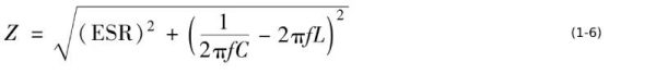 4.4.3 Measurement of impedance
The Z of the aluminum electrolytic capacitor is tested under the equivalent series circuit at 25°C under a measuring bridge powered by a variable frequency power supply with an AC signal voltage of tunable between 10Hz and 100kHz with an effective value of 1V. Impedance measurements are mainly typical characteristic curves and low temperature limit measurements.
For low temperature impedance measurement, place the capacitor in the temperature control box and set the low temperature limit to ±2°C. The impedance is measured at a frequency of (120±5) Hz using any suitable method providing an accuracy of ±2.5%. As soon as possible after the temperature has stabilized, the measurement should be made with the lowest possible AC measurement voltage so that it does not cause the capacitor to heat up. The capacitor is assumed to be thermally stable if two consecutive measurements taken 15 minutes apart show no change
4.4.4 Impedance temperature characteristics
As can be seen from Figure 1-6, the capacitive impedance temperature characteristics of aluminum electrolytic capacitors and the inductive reactance temperature characteristics due to parasitic inductance basically do not change with temperature. The impedance temperature characteristics only change greatly with temperature when ESR plays a major role. , which is determined by the temperature characteristics of the resistivity of the electrolyte
4.4.5 Equivalent series inductance
The equivalent series inductance is relatively independent of frequency and temperature, with typical values ranging from 2 to 8nH (surface mount), 10 to 30nH (radial lead), and 20nH (axial lead). These inductance values vary with the number of lead-out electrode positions and the lead-out method.
4.4.6 Resonant frequency
The resonant frequency is the frequency when the capacitive reactance 1/(2πfC) is equal to the inductive reactance 1/(2πfL). This is because the capacitive reactance and the inductive reactance are 180° out of phase, the two reactances cancel out, and the remaining impedance is pure resistance, which is equal to the ESR at this frequency. For aluminum electrolytic capacitors, the typical value of the resonant frequency should be much higher than the rectification and filtering frequency of the 120Hz capacitor. The resonant frequency of current aluminum electrolytic capacitors is generally above 20kHz, which is sufficient for power frequency rectification and filtering, but for high frequency The filtered resonant frequency can reach more than 100kHz.
4.5 Performance Analysis of Electrolytic Capacitors-Summary
Electrolytic capacitors are used as filter components, and their capacitive reactance, ESL, and ESR determine the filtering effect of electrolytic capacitors. In the low frequency band, the capacitive reactance of the electrolytic capacitor is much greater than ESR and ESL. At this time, the capacitive reactance of the electrolytic capacitor determines the filtering effect. In this state, sufficient capacitance is required to ensure a low enough capacitive reactance.
As the frequency increases, the capacitive reactance decreases. When the capacitive reactance of the electrolytic capacitor is close to the ESR or even lower than the ESR, the filtering effect will depend on the ESR. Since the ESR of electrolytic capacitors is relatively large, the frequency range in which ESR determines the filtering effect may be relatively wide. The larger the ESR, the wider the frequency band that affects the filtering effect. This is why high-frequency, low-resistance electrolytic capacitors are needed.
If it is also low resistance in the low frequency band, it can effectively increase the ESR under 120Hz conditions, reduce the loss factor, and increase the ripple current tolerance at 120Hz.
As the frequency continues to increase, the inductive reactance of the electrolytic capacitor ESL increases to a point that cannot be ignored, and the filtering effect will depend on the ESL. Therefore, the lower the ESL, the better the high-frequency filtering effect. Using multiple sets of conductor strips to lead out electrodes at appropriate locations on the aluminum foil will partially or mostly offset the winding parasitic inductance. Using a negative extension will significantly reduce the parasitic inductance of the electrolytic capacitor.
The actual negative electrode of the electrolytic capacitor is the electrolyte. The ESR of the low-frequency band of the electrolytic capacitor is mainly the equivalent ESR of the aluminum oxide film when alternating current is applied. As the frequency increases, the equivalent ESR of the aluminum oxide film decreases, and the equivalent ESR of the electrolyte begins to take effect. Since the electrolyte is ionically conductive, the equivalent ESR will change with temperature. The lower the temperature, the greater the equivalent ESR. The higher the temperature (not exceeding the maximum ambient temperature in the data sheet), the lower the equivalent ESR. The highest temperature and the lowest temperature are The temperature electrolyte equivalent ESR differs by more than an order of magnitude. The performance of liquid electrolytic capacitors at low temperatures (close to the minimum operating temperature in the datasheet) is poor relative to room temperature
The above is about the performance analysis of electrolytic capacitors—impedance frequency characteristics of electrolytic capacitors
5 Performance Analysis of Electrolytic Capacitors -Ripple Current Withstanding Capability
5.1 Performance Analysis of Electrolytic Capacitors-Origin of ripple current withstanding capability
The initial electrolytic capacitors were used in general electronic circuits. In this application state, the AC current flowing through the electrolytic capacitors was low. At this time, it seemed unnecessary to consider the current carrying capacity of the electrolytic capacitors. Therefore, the data sheets of early electrolytic capacitors There is no such data. Electrolytes with higher resistivity in boric acid are also acceptable.
When electrolytic capacitors are mainly used in power electronic circuits such as switching power supplies, the working status of electrolytic capacitors has changed. The most important change is that the unit capacitance current flowing through the electrolytic capacitor surges, causing the “internal resistance” of the electrolytic capacitor to heat up, eventually leading to early failure of the electrolytic capacitor, or even failure very quickly. Therefore, the electrolytic capacitor has the ability to withstand ripple current. Referred to as ripple current. The term ripple current is transplanted from ripple voltage. After the alternating current is rectified and filtered, the voltage becomes a relatively stable direct current, but there is still an alternating current component superimposed on the direct current voltage, and the waveform is like ripples on the water surface. For voltage, this calm “water surface” is the DC voltage component, and the “ripple” is the AC component superimposed on the DC voltage, that is, the ripple voltage.
The same is true for current. The AC current output by rectification is called ripple current. For the DC load end, this ripple current is not required or even allowed, so the ripple current must “all” flow into the electrolytic capacitor. Therefore, the effective current value capability of the electrolytic capacitor is called ripple current.
5.2 Ripple current withstanding capability
The AC ripple current flowing through the aluminum electrolytic capacitor will cause losses in its ESR and cause the aluminum electrolytic capacitor to heat up. This heating limit limits the ripple current to the rated ripple current value. It is defined as the maximum ripple current value that can ensure the rated life time of the aluminum electrolytic capacitor at the highest operating temperature. For aluminum electrolytic capacitors used in general applications, most aluminum electrolytic capacitor manufacturers do not give rated ripple current data. For low ESR aluminum electrolytic capacitors used in switching power supplies or pin-type aluminum electrolytic capacitors with larger capacitance, they give this data.
In fact, the ripple current that aluminum electrolytic capacitors can withstand is relatively low. The first impression of the ripple current value that general-purpose aluminum electrolytic capacitors can withstand is that it is too low. Fortunately, most applications do not require very high requirements. ripple current
5.3 Definition of rated ripple current
At the highest ambient temperature, the current flowing through the electrolytic capacitor causes the center temperature of the electrolytic capacitor core to rise. The ripple current value corresponding to the rated temperature rise is the rated ripple current.
Electrolytic capacitors with different maximum temperatures have different temperature rises. For example, an electrolytic capacitor with a maximum temperature of 105°C has a rated ripple current of 10°C, while an electrolytic capacitor with a maximum temperature of 105°C has a rated ripple current of 10°C. The corresponding temperature rise is 5°C. This different result is because the maximum operating temperature of the 85°C electrolyte should generally not exceed 95°C, while the maximum operating temperature of the 105°C electrolyte should generally not exceed 110°C.
Based on the above habits, even if a 105°C electrolytic capacitor is manufactured with a 125°C electrolyte, the rated ripple current temperature rise is still 5°C.
The temperature rise under the rated ripple current of electrolytic capacitors with a maximum temperature of 125°C or 130°C or even 144°C or 150°C is generally limited to 5°C.
To sum up, the essence of the rated ripple current parameter is the limitation of the heating of the electrolytic capacitor core caused by the ESR of the ripple current flowing through the electrolytic capacitor
5.4 Ripple current frequency characteristics
As can be seen from Figure 1-6, the ESR of the electrolytic capacitor changes with frequency. From the same perspective as the heating of electrolytic capacitors, as the frequency increases, the ESR decreases. If the ripple current remains unchanged, the loss of the electrolytic capacitor itself decreases, and the temperature rise decreases accordingly. At this time, if you want to achieve the same temperature rise, you can increase the ripple current so that the loss caused by the ripple current on the ESR of the electrolytic capacitor is the same as that under the “standard conditions” of 120Hz. The corresponding multiplication factor is the frequency of the ripple current. Conversion factor. The frequency conversion coefficient of the ripple current of a certain electrolytic capacitor is shown in Table 1-1.
Table 1-1 Frequency conversion coefficient of ripple current of an electrolytic capacitor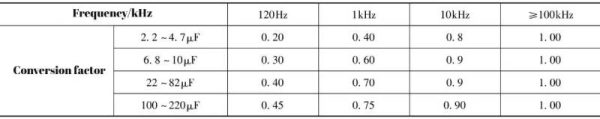 As can be seen from Table 1-1, the benchmark test frequency of this electrolytic capacitor is 100kHz, that is, when tested at a frequency of 100kHz, the rated ripple current of the electrolytic capacitor is “1”. Under the same temperature rise conditions, the corresponding ripple currents at other frequencies are converted coefficients.
At the same frequency: the smaller the capacitance, the smaller the conversion coefficient obtained; the lower the frequency, the smaller the conversion coefficient obtained. The pattern is consistent with ESR increasing as frequency decreases. Similarly, the lower the frequency band, the faster the ESR of the electrolytic capacitor increases, so the rated ripple current in this frequency band attenuates faster.
Table 1-1 does not list the attenuation degree of the ripple current at the 50Hz frequency. As can be seen from Figure 1.2, the rated ripple current attenuates more obviously. If the frequency continues to be reduced, there will be little corresponding rated ripple current left. Therefore, electrolytic capacitors need to try their best to avoid the existence of ultra-low frequency ripple current.
The frequency conversion factor of the ripple current of the electrolytic capacitor can also be based on 120Hz. Table 1-2 shows the conversion coefficient of the ripple current frequency of an electrolytic capacitor based on 120Hz as the test standard.
Table 1-2 Frequency conversion coefficient of ripple current of an electrolytic capacitor based on 120Hz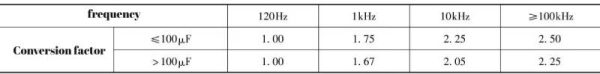 As can be seen from Table 1-2, when tested at a frequency of 120Hz, the rated ripple current of the electrolytic capacitor obtained is “1”. Under the same temperature rise conditions, the corresponding ripple currents at other frequencies are converted coefficients.
At the same frequency: the smaller the capacitance, the greater the conversion coefficient obtained; the lower the frequency, the smaller the conversion coefficient obtained. This is consistent with ESR increasing as frequency decreases. Similarly, the lower the frequency band, the faster the ESR of the electrolytic capacitor increases, so the rated ripple current in this frequency band increases faster.
It should be noted that the current conversion factor based on 100kHz is generally feasible. However, for lead-pin electrolytic capacitors, the ripple current frequency conversion coefficients calculated back to 1kHz, 10kHz, and 100kHz based on 120Hz are not necessarily correct. It is very likely that the following situation will occur: under the condition of 100kHz, multiply the ripple current at the 120Hz reference frequency by the frequency conversion factor, and it will be concluded that the ripple current life of the electrolytic capacitor under the converted 100kHz condition is shorter than that under the 120Hz reference ripple current condition. life span. The reason is that the electrolytic capacitor has winding parasitic inductance. This parasitic inductance will quickly attenuate the current of the aluminum foil at the far end of the guide pin or guide bar, causing the current to be too concentrated near the guide pin or guide bar, resulting in Aluminum foil is severely overcurrent.
5.5 Ripple current temperature characteristics
It can be seen from Table 1-3 that as the core temperature of the electrolytic capacitor increases, the ESR of the electrolytic capacitor decreases. For the same temperature rise, the rated ripple current can increase. The degree of increase is the temperature conversion coefficient of the ripple current. Most small electrolytic capacitors do not give a temperature conversion factor for ripple current.
The temperature conversion coefficient given for the electrolytic capacitor (105℃/4000h) shown in Table 1-3 is based on 85℃. The reason is that the rated ripple current of this electrolytic capacitor is given at 85℃. It can be seen from the table that as the ambient temperature decreases, the temperature conversion coefficient of the ripple current of this electrolytic capacitor increases. At 45°C, it reaches 2 times that of 85°C and 4 times that of 105°C!
Table 1-3 Temperature conversion coefficient of ripple current of lead-pin electrolytic capacitor (CDE361R series) The temperature conversion coefficient given for the electrolytic capacitor (85℃/3000h) shown in Table 1-4 is based on 85℃. It can be seen from the table that as the ambient temperature decreases, the temperature conversion coefficient of the ripple current of this electrolytic capacitor increases, reaching 1.5 times that at 85°C at 45°C.
Table 1-4 Temperature conversion coefficient of ripple current of pin-type electrolytic capacitor (CDE380 series) The temperature conversion coefficient given for the electrolytic capacitor (85℃/8000h) shown in Table 1-5 is based on 85℃. As can be seen from the table, as the ambient temperature decreases, the temperature conversion coefficient of the ripple current of this electrolytic capacitor increases, reaching 1.8 times that at 85°C at 45°C.
Table 1-5 Temperature conversion coefficient of ripple current of bolt-type electrolytic capacitor (CDE520C series) However, it should be noted that when the electrolytic capacitor is applied to the ripple current value after passing the temperature conversion coefficient, regardless of the ambient temperature, the life is the rated high temperature load life. When the ambient temperature is lower than the maximum rated ambient temperature, as the temperature decreases by 10°C, the rule of doubling the lifespan no longer exists. Therefore, it is absolutely unrealistic to try to use the ambient temperature to be much lower than the maximum rated temperature to increase the actual ripple current, while also trying to obtain a long life at a low ambient temperature!
5.6 Nature of rated ripple current
The rated ripple current is actually the limit of the temperature rise caused by the ripple current flowing through the electrolytic capacitor. This limitation is mainly due to the service life of the electrolytic capacitor.
If the ripple current flowing through the electrolytic capacitor exceeds the rated ripple current, the electrolytic capacitor can still work normally to a certain extent, but the life will be shortened. The greater the ripple current, the shorter the life, and the life is shortened much faster. higher than the rate at which the ripple current increases.
Continuing to increase the ripple current can cause the electrolytic capacitor to heat up severely in a short period of time and generate gas in the electrolytic capacitor. Under such working conditions, the gas pressure inside the electrolytic capacitor is getting higher and higher, which will eventually burst the explosion-proof valve of the electrolytic capacitor. In mild cases, the electrolytic capacitor will appear as a convex bottom. In severe cases, the explosion-proof valve of the electrolytic capacitor will be opened wide and spray out. Electrolyte, that is, bursting pulp, will be accompanied by broken capacitor paper when the electrolyte is sprayed out. The most serious situation is an electrical spark between the guide pin or guide bar and the aluminum foil, resulting in implosion (only one of the causes of implosion)
The above is the performance analysis of electrolytic capacitors—ripple current endurance
6 Performance Analysis of Electrolytic Capacitors-relationship between life and temperature and ripple current
6.1 Performance Analysis of Electrolytic Capacitors-The relationship between the service life of lead-pin electrolytic capacitors, temperature and ripple current
The actual service life of the electrolytic capacitor is related to the working conditions of the electrolytic capacitor, mainly related to temperature and ripple current. Electrolytic capacitors with different packages, rated voltages, and capacitances have different relationships between life, temperature, and ripple current, as shown in Figure 1-9. The ordinate in the figure is the ratio of the actual ripple current to the rated ripple current when the ambient temperature (or case temperature) is 105°C. The abscissa is the ambient temperature. The case temperature curve of this electrolytic capacitor is basically the same as the ambient temperature curve.
Figure 1-9 shows a low-voltage, high-frequency, low-resistance electrolytic capacitor with diameters of 10mm (105℃/5000h) and 12.5mm (105℃/7000h) with same-side leads. The shaded area in the figure is a prohibited working area. Once the electrolytic capacitor enters this area, there is no guarantee whether the electrolytic capacitor will fail.
Comparing the curves in Figure 5-9a and b, the life of small-diameter electrolytic capacitors (5000h) is shorter than that of large-diameter electrolytic capacitors (7000h). The reason is that large-diameter electrolytic capacitors contain more electrolyte than small-diameter electrolytic capacitors. It can also be seen that when the ambient temperature is 40°C, the effective limit ripple current of a 10mm diameter electrolytic capacitor is greater than that of a 12.5mm diameter electrolytic capacitor. The former is about 3.2 times the rated ripple current, and the latter is about 2.75 times the rated ripple current.
Under the rated ripple current condition, when the temperature drops by 25°C, the life span is extended to 8 times the original value. For every 8°C drop in ambient temperature, the life span is doubled.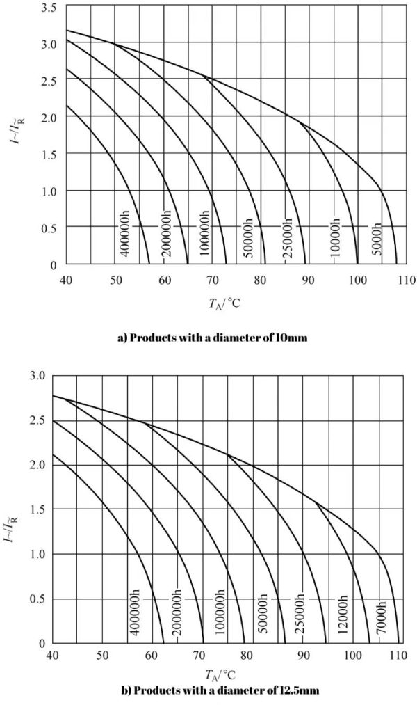 Figure 1-9 The relationship between the life of B41888 series electrolytic capacitors, temperature and ripple current
Taking the 12.5mm product as an example, when the ambient temperature of the electrolytic capacitor is 65°C, the life span under the rated ripple current state is 200,000 hours; when the ripple current rises to about 1.7 times the rated ripple current, the life span drops to 10 10,000 h; while the ripple current at the 50,000 h life span only requires 2.2 times the rated ripple current; the ultimate ripple current is approximately 2.35 times the rated ripple current! The life span at this time should be reduced to 7000h. It can be seen that as the ripple current increases, the life of the electrolytic capacitor decreases under the same temperature conditions. When the ripple current rises to more than 1.5 times the rated ripple current, the life of the electrolytic capacitor shortens faster and faster until it exceeds the limit. Ripple current may cause convex bottom or even explosion.
6.2 The relationship between the service life of axial leaded electrolytic capacitors, temperature and ripple current
The advent of axial lead type electrolytic capacitors preceded the same side lead (lead pin type) electrolytic capacitors. Generally speaking, axial lead electrolytic capacitors perform better than same-side lead electrolytic capacitors, but same-side lead electrolytic capacitors are more suitable for automated mass production and are cheaper.
The relationship between the life of the B36697 series electrolytic capacitors, temperature and ripple current is shown in Figure 1-10.
 Figure 1-10 The relationship between life and temperature and ripple current of B36697 series electrolytic capacitors
Since B43697 is a high-voltage electrolytic capacitor, its limit overcurrent multiple is lower than the limit overcurrent multiple given in Figure 1-9.
As can be seen from Figure 1-10, for high-voltage electrolytic capacitors, appropriately reducing the operating voltage can effectively extend its life. Even a 6.6% reduction will extend the life from the rated life of 4000h to 11500h.
6.3 The relationship between the service life of automotive grade electrolytic capacitors, temperature and ripple current
Since automotive-grade electronic devices need to work between -40 and 120°C, fuel-engine vehicles require that the maximum operating temperature of automotive-grade electrolytic capacitors needs to be 125°C or even 150°C.
Figure 1-11 shows the relationship between the life of the B3693 series of automotive grade electrolytic capacitors, temperature and ripple current.
This is a low-voltage, high-frequency, low-resistance electrolytic capacitor. The ripple current limit curve (the boundary between the shaded and non-shaded areas) is similar to Figure 1-7.
Figure 1-11a shows the relationship between life and ambient temperature and ripple current. Figure 1-11b shows the relationship between life and case temperature and ripple current. The latter has a slightly larger ripple current limit than the former, reaching the rated ripple current. Nearly 3.3 times, an increase of about 10%. At the same time, the equal life curve in Figure 1-11b becomes steeper. Even if the ripple current is the same, the life span will be longer as measured by the case temperature.
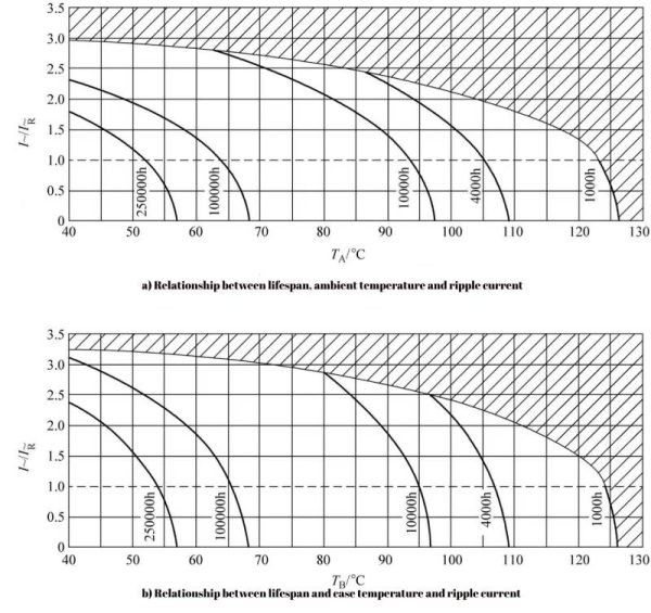 Figure 1-11 The relationship between the service life and temperature and ripple current of the B3693 series of automotive grade electrolytic capacitors
6.4 Relationship between the service life of pin-type electrolytic capacitors, temperature and ripple current
Figure 1-12 shows the relationship between life and temperature and ripple current of the B43504 series of pin-type electrolytic capacitors.
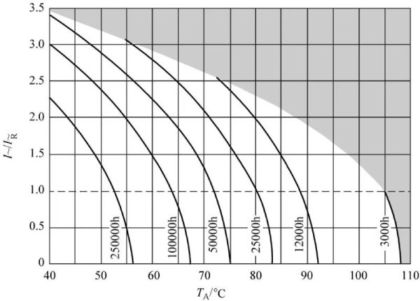 Figure 1-12 The relationship between life and temperature and ripple current of the B43504 series
As can be seen from Figure 1-12, the isothermal life curve is relatively steep, which may be the result of the extension of the negative electrode improving the thermal conductivity, and the limit ripple current is close to 3.5 times the rated ripple current.
6.5 Relationship between the service life of bolt-type electrolytic capacitors, temperature and ripple current
Figure 1-13 shows the relationship between the service life of the bolt-type electrolytic capacitor B43560 series and the temperature and ripple current.
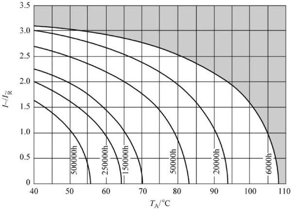 Figure 1-13 The relationship between life and temperature and ripple current of bolt-type electrolytic capacitor B43560 series
The above is the performance analysis of electrolytic capacitors—the relationship between life, temperature and ripple current
7 Performance Analysis of Electrolytic Capacitors- Thermal Effect of ESR and Thermal Resistance of Aluminum Electrolytic Capacitors
The ripple current flowing through the ESR of the aluminum electrolytic capacitor will produce a power loss of p=i2R ESRand cause the aluminum electrolytic capacitor to heat up. Compared with power semiconductor devices, aluminum electrolytic capacitors have very poor heat dissipation capabilities, so the internal temperature of aluminum electrolytic capacitors with slight power consumption will increase significantly, thereby reducing the service life of aluminum electrolytic capacitors. Therefore, in addition to understanding the impact of the ESR of aluminum electrolytic capacitors on circuit operation, we must also pay attention to the heat dissipation ability of aluminum electrolytic capacitors, that is, the thermal resistance.
In large aluminum electrolytic capacitors, a large ripple current usually flows, causing the aluminum electrolytic capacitor to heat up. In order to dissipate the heat generated by the aluminum electrolytic capacitor, the temperature of the aluminum electrolytic capacitor core pack will be higher than the temperature of the shell, that is, the temperature from the shell to the core pack of the aluminum electrolytic capacitor increases. This temperature rise is very important and determines the working status and life of the aluminum electrolytic capacitor. If you know the heat dissipation capacity (thermal resistance) of the aluminum electrolytic capacitor from the core pack to the shell, it is easy to calculate whether the temperature of the aluminum electrolytic capacitor core pack is within the desired value or design requirement range through the measured ripple current and shell temperature. The packaging forms of aluminum electrolytic capacitors are mainly divided into three categories: bolt type (large aluminum electrolytic capacitors or high ripple current aluminum electrolytic capacitors), pin type (medium aluminum electrolytic capacitors or medium ripple current aluminum electrolytic capacitors), lead type and Surface mount (small aluminum electrolytic capacitors or low ripple current aluminum electrolytic capacitors). Tables 5-6 to 5-9 respectively show the thermal resistance data of bolt-type aluminum electrolytic capacitors produced by CDE Company, the thermal resistance data of bolt-type aluminum electrolytic capacitors produced by RIFA Company, and the thermal resistance data of pin-type aluminum electrolytic capacitors produced by CDE Company. Thermal resistance data of pin-type aluminum electrolytic capacitors produced by RIFA.
The above is about the performance analysis of electrolytic capacitors—The thermal effect of ESR and the thermal resistance of aluminum electrolytic capacitors
Table 1-6 Thermal resistance data of bolt-type aluminum electrolytic capacitors produced by CDE Company (unit: ℃/W)
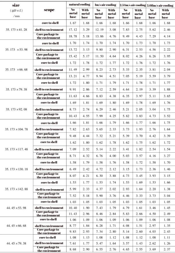
(continued)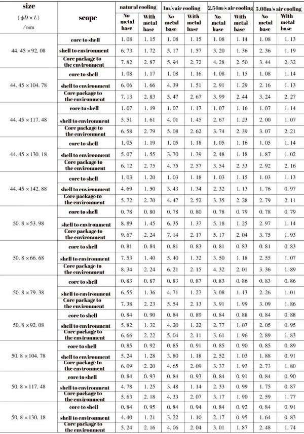
(continued)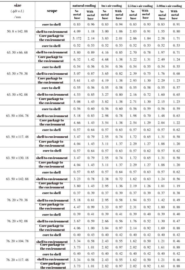
(continued)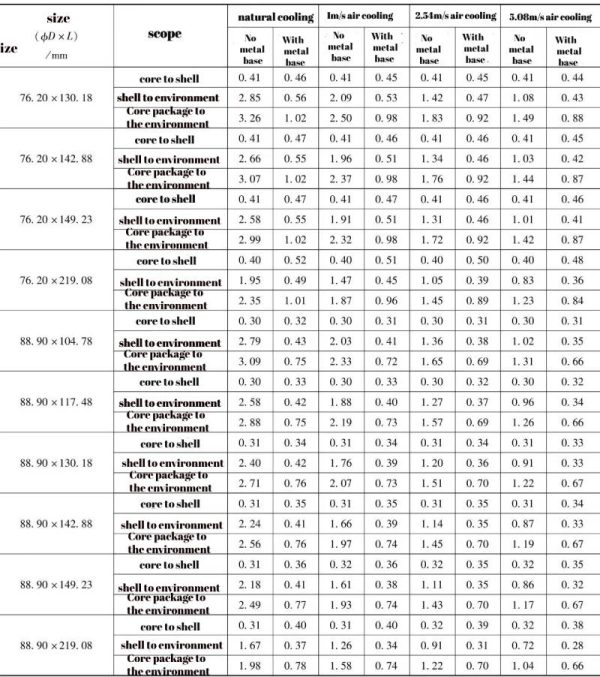
Note: The metal base in the table is to fix the aluminum electrolytic capacitor on a radiator or metal chassis with heat dissipation capability.
Table 1-7 Thermal resistance data of bolt-type aluminum electrolytic capacitors produced by RIFA (Unit: °C/W)
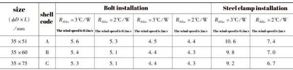 (continued)
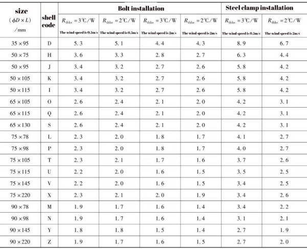
Note: Rthhs in the table is the thermal resistance from the aluminum electrolytic capacitor shell to the radiator.
Table 1-8 Thermal resistance data of pin-type aluminum electrolytic capacitors produced by CDE (unit: ℃/W)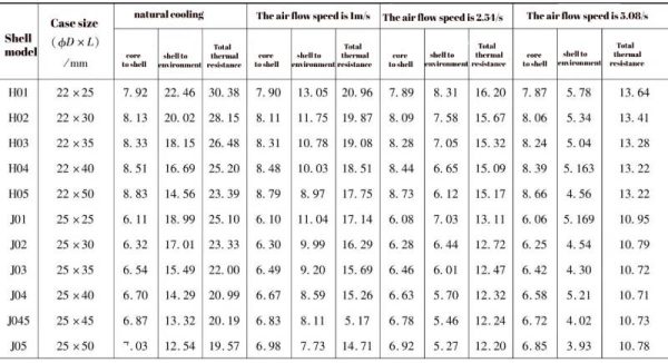
(continued)
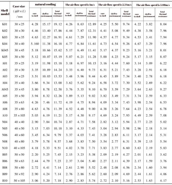 Table 1-9 Thermal resistance data of pin-type aluminum electrolytic capacitors produced by RIFA (ambient temperature 40°C)
(continued)
 Through the comparison between Table 1-6 and Table 1-7 and the comparison between Table 1-8 and Table 1-9, we can see that the shells of the same manufacturer have the same size and shape, and the thermal resistance from the shell to the environment is basically the same, but different aluminum electrolytic The thermal resistance from the core package to the shell of aluminum electrolytic capacitors produced by capacitor manufacturers is very different. The main reason is that the manufacturing processes of each aluminum electrolytic capacitor manufacturer are different. If the electrolyte only infiltrates the aluminum electrolytic capacitor core package but does not fill the entire interior of the casing, there will be gas with poor thermal conductivity between the core package and the casing, and the thermal resistance will be high. European aluminum electrolytic capacitor manufacturers that focus on reliability and long life fill the aluminum electrolytic capacitor with electrolyte (i.e. liquid aluminum electrolytic capacitor). There is an electrolyte with good thermal conductivity between the core package and the shell. The thermal resistance is greatly reduced, and the aluminum electrolytic capacitor allows The ripple current flowing through is also greatly increased.
Another effective way to reduce the thermal resistance from the core to the shell of an aluminum electrolytic capacitor is to “sit” the negative aluminum foil of the aluminum electrolytic capacitor directly on the shell to increase the thermal conductivity and reduce the thermal resistance from the core to the shell.
From the above analysis, we can see that for products produced by different aluminum electrolytic capacitor manufacturers, products with the same appearance or similar shells have basically the same thermal resistance from the shell to the environment, but the thermal resistance from the core package to the shell is quite different. If only considered from a quality perspective, the thermal resistance from the core package to the shell of the aluminum electrolytic capacitor reflects the application quality of the aluminum electrolytic capacitor.
Among the many aluminum electrolytic capacitor manufacturers in the world, few can provide the thermal resistance of their aluminum electrolytic capacitors. Some do not have this data (such as many domestic aluminum electrolytic capacitor manufacturers), while others require technical confidentiality.
The size and rated ripple current of leaded aluminum electrolytic capacitors are very small, and they can usually meet the requirements of designing electronic circuits without considering thermal resistance.
Summarize
Performance Analysis of Electrolytic Capacitors-—mainly including ripple current tolerance, equivalent series resistance, equivalent series inductance and other parameters….To learn more about electrolytic capacitors and products, please click:www.xuanxcapacitors.com