Capacitors are represented by the letter “C” in circuits. The unit of capacitance is “farad”, referred to as “law”, represented by the letter “F”. In practice, “microfarad” (expressed in “μF”), “nanofarad” (expressed in “nF”) or picofarad (expressed in “pF”) is more commonly used. The conversion relationship between them is: 1F=10^6μF=10^9nF=10^12pF. Identify capacitors is an important link before detecting capacitors. It mainly includes the identification of capacitor circuit identification, the identification of capacitor direct label identification, digital identification, and color ring identification, and the distinction of the polarity of electrolytic capacitor pins.
1.1 Identification of capacitor circuit identification
The identification of capacitors in the circuit is usually divided into two parts: one part is the circuit graphic symbol, indicating the type of capacitor; the other part is letters + numbers, indicating the serial number and main parameters of the capacitor in the circuit.Figure 3-19 provides an example illustration showcasing the process to identify capacitors in this manner.
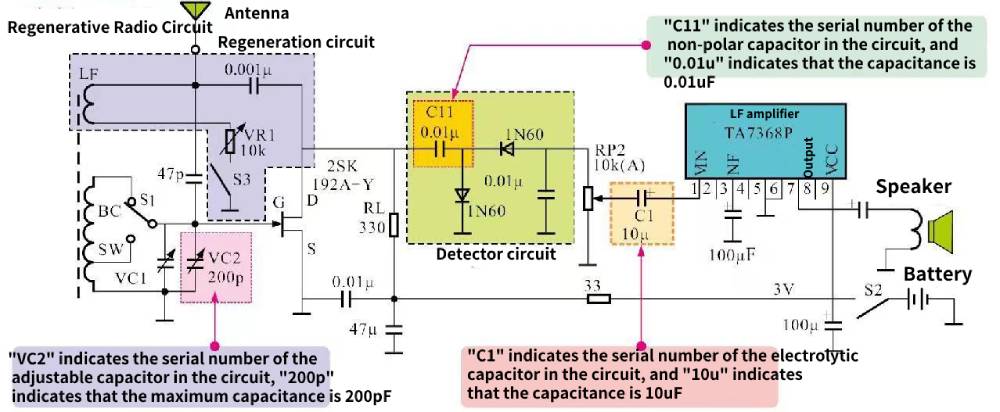
Figure 3-19 Identification of capacitors in the circuit
1.2 Recognition of direct labeling of capacitors
To facilitate the identification of capacitors, the direct marking method is commonly employed, whereby specific code symbols are imprinted on the capacitor’s shell. These symbols utilize a combination of numbers and letters to indicate the capacity value and main parameters of the capacitor. In accordance with my country’s national standards, the model identification of capacitors is typically divided into six parts. Figure 3-20 serves as a visual guide, illustrating the precise method to identify capacitors through the direct mark identification information. By referencing this figure, one can easily interpret the alphanumeric codes and accurately identify capacitors based on their designated characteristics and specifications.
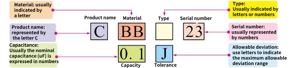
Figure 3-20 Recognition method of capacitor direct mark identification information
See Table 3-2 for the meanings of the relevant letters representing materials in the capacitor direct labeling method, and see Table 3-3 for the meanings of the allowable deviation letters. Mastering the corresponding meanings of these symbols can successfully complete the reading of direct-labeled capacitors.
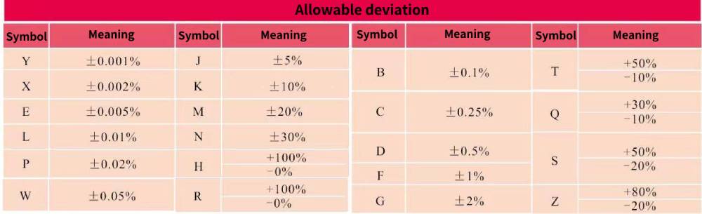
Table 3-3 Meanings of allowable deviation letters in capacitor direct marking method
1.3 Recognition of digital identification of capacitors
Digital identification is an approach that utilizes numbers or a combination of numbers and letters to label the main parameter values of capacitors. This method allows for clear and precise identification of capacitor characteristics. Figure 3-21 illustrates the reading method for identifying capacitor parameters using the digital labeling technique. By referring to this figure, one can easily identify capacitors by interpreting the numerical or alphanumeric codes associated with their specific parameter values. This facilitates accurate recognition and understanding of the capacitor’s key specifications.
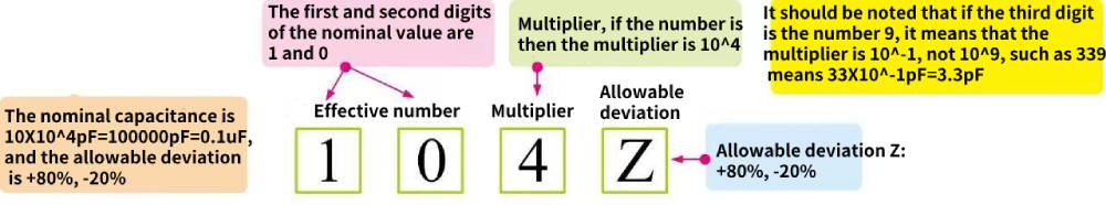
Figure 3-21 The reading method of the digital labeling method of capacitor parameters
The numerical notation of capacitors is similar to the direct notation of resistors. Among them, the first two digits are effective figures, the third digit is the multiplier, and the following letters are the allowable error, and the default unit is pF. For the meaning of the letter in the specific allowable deviation, please refer to the allowable deviation of the resistor above.
1.4 Recognition of capacitor color ring logo
Some capacitors have the same appearance as color ring resistors, and these capacitors are called color ring capacitors. These color rings mark the parameter information of capacitors in different colors. In general, the color rings of different colors have different meanings, and the color rings of the same color have different meanings at different positions.
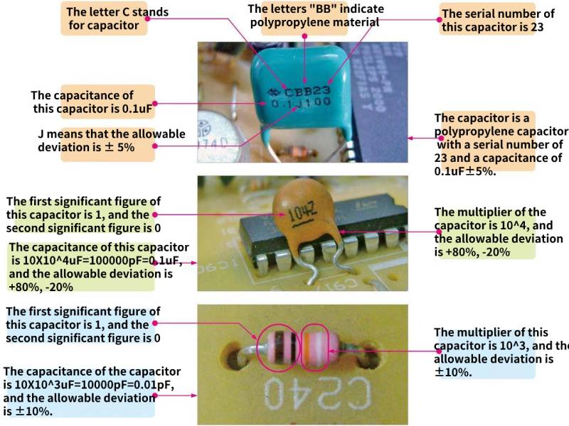
Figure 3-23 Example of reading common capacitor parameter information
In addition to the above methods of capacitor parameter identification, some capacitor parameters are directly marked, that is, the parameters such as capacitance, rated operating voltage, and allowable deviation are directly marked on the capacitor shell, and can be read directly according to the mark. As shown in Figure 3-24.
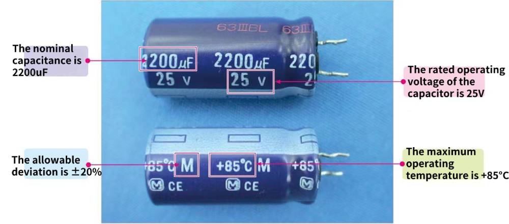
Figure 3-24 Parameter reading of capacitors using the direct marking method
The main parameters of capacitors are nominal capacity (capacitance), allowable deviation, rated working voltage, insulation resistance, temperature coefficient and frequency characteristics.
◇The nominal capacity of a capacitor refers to the size of the ability to store charges after adding a voltage. Under the same voltage, the more charges are stored,
The larger the capacity of the capacitor.
◇There is a certain deviation between the actual capacity of the capacitor and the nominal capacity. The allowable maximum deviation range between the nominal capacity of the capacitor and the actual capacity is called the allowable deviation of the capacitance. The allowable deviation of capacitors can be divided into three grades: Grade I ±5%; Grade II ±10%; Grade III ±20%.
◇Rated voltage refers to the highest voltage at which the capacitor can work continuously and reliably within the specified temperature range, and is sometimes divided into rated DC working voltage and rated AC working voltage (effective value). The rated voltage is a reference value. In actual use, if the working voltage is greater than the rated voltage of the capacitor, the capacitor will be easily damaged and will be in a breakdown state.
◇The insulation resistance of a capacitor is equal to the ratio of the voltage applied across the capacitor to the leakage current through the capacitor. The insulation resistance of a capacitor is related to factors such as the dielectric material and area of the capacitor, the material and length of the lead wire, the manufacturing process, temperature and humidity. For capacitors of the same medium, the larger the capacitance, the smaller the insulation resistance. If it is an electrolytic capacitor, the dielectric coefficient is often used to express the insulation capacity characteristics of the capacitor.
◇ Temperature coefficient refers to the relative change value of capacitance for every 1°C change in temperature within a certain temperature range. The temperature coefficient of the capacitor is represented by the letter αC, which is mainly related to the structure of the capacitor and the temperature characteristics of the dielectric material.
The temperature coefficient can be divided into positive and negative. The positive temperature coefficient indicates that the capacitance increases with the increase of temperature; the negative temperature coefficient indicates that the capacitance decreases with the increase of temperature. In use, whether it is a positive temperature coefficient or a negative temperature coefficient, the smaller the better. ◇Frequency characteristic refers to the nature of the capacitance and other parameters of the capacitor changing with the frequency of the electric field under the working state of the AC circuit or high-frequency circuit.
1.5 Identify the polarity of capacitor pins
The polarity of the pins of electrolytic capacitors can generally be distinguished from three aspects: one is based on the color or symbol identification on the shell; the other is based on the length of the capacitor pins or the external obvious identification; the third is based on the circuit Board symbol or circuit graphic symbol recognition.
Some electrolytic capacitor shells are obviously marked with negative polarity pin marks, such as “-” symbols or black marks, and usually the end with these marks is the negative polarity pin of the electrolytic capacitor, as shown in Figure 3-25.
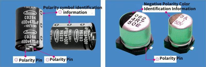
Figure 3-25 Differentiate the polarity of the pins of electrolytic capacitors according to the color and symbol
Before the electrolytic capacitor is installed, its lead length is not consistent, and the longer lead is the positive polarity lead. Some electrolytic capacitors have obvious gaps near the positive polarity pins. It is very simple to distinguish the polarity of the capacitor pins according to this feature, as shown in Figure 3-26.
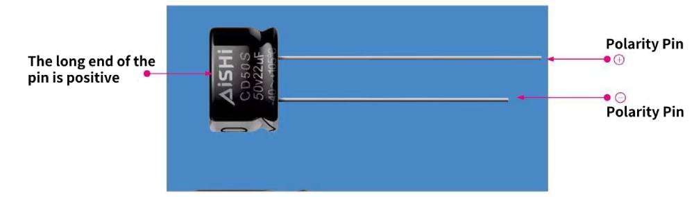
Figure 3-26 Identify the lead polarity of an electrolytic capacitor based on the lead length
If the electrolytic capacitor is installed on the circuit board, there is usually a polarity symbol or a circuit graphic symbol printed near it, and the polarity of the pins of the capacitor can be easily identified according to the circuit graphic symbol, as shown in Figure 3-27.
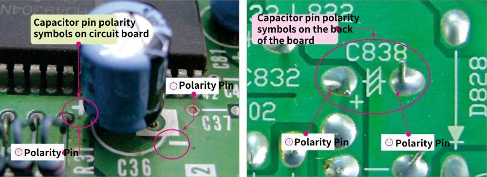
Figure 3-27 Identify the pin polarity of the electrolytic capacitor according to the circuit board symbol or circuit graphic symbol